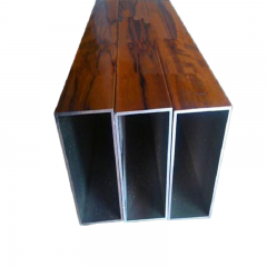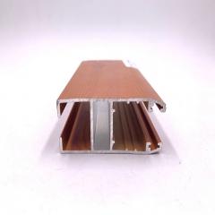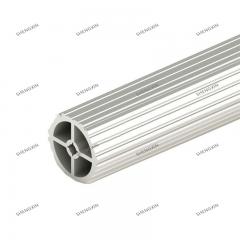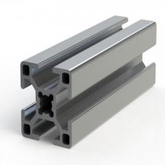
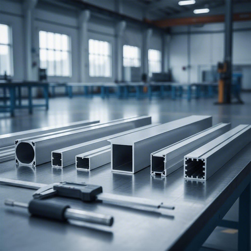
Have you ever received a batch of extruded aluminum profiles only to discover they don't quite fit your assembly? Or perhaps you've watched a project timeline slip because components needed rework after delivery? These frustrating scenarios often trace back to one overlooked element: aluminum extrusion tolerances.
For engineers, designers, and procurement professionals working with extruded aluminum, understanding these specifications isn't just technical knowledge—it's the difference between a smooth production run and costly delays. Yet tolerance information remains scattered across industry documents, leaving many professionals piecing together fragmented guidance.
Simply put, aluminum extrusion tolerances define the acceptable deviation from nominal dimensions in extruded profiles. When you specify a wall thickness of 3.0 mm, for example, the actual manufactured part won't measure exactly 3.000 mm. Tolerances establish the acceptable range—perhaps 2.9 mm to 3.1 mm—within which the part remains functional and acceptable.
According to industry standards, these limits of variation are mutually agreed between manufacturers and customers before production begins. Tolerances appear on engineering drawings as plus or minus decimal fractions of millimeters (or inches) and apply to various aluminum extrusion dimensions including cross-sectional features, wall thicknesses, and delivered lengths.
The aluminum extrusion definition of tolerance encompasses more than just size. It includes geometric characteristics like straightness, twist, and flatness—each critical to how your profiles will perform in real-world applications. Different aluminum extrusion sizes require different tolerance considerations, as larger profiles present unique challenges compared to smaller ones.
Imagine ordering thousands of extruded channels for a structural assembly, only to find they're slightly out of spec. The consequences cascade quickly: rejected parts, production halts, rush orders for replacements, and missed deadlines. This scenario plays out more often than you'd think when tolerance specifications aren't properly understood or communicated.
Tolerances protect both the manufacturer and the customer—they let extruders know how much they can deviate from specified dimensions for the part to work properly, while preventing costly rejections of otherwise functional components.
Several key factors affect achievable tolerances in aluminum extrusions:
Understanding these aluminum extrusion tolerances upfront helps you design parts that manufacturers can actually produce consistently. It also prevents the common mistake of over-specifying—requesting tighter tolerances than your application truly requires, which drives up costs unnecessarily.
This guide consolidates the fragmented industry information into a single, comprehensive resource. You'll learn about governing standards, tolerance categories, classification systems, and practical specification strategies. Whether you're selecting from standard aluminum extrusion sizes or developing custom profiles, the knowledge ahead will help you get tolerance specifications right the first time.

So you understand what tolerances are and why they matter—but where do the actual numbers come from? The answer lies in a framework of industry standards that manufacturers and engineers reference worldwide. Knowing which standard applies to your project helps you communicate requirements clearly and ensures your specifications align with what suppliers can actually deliver.
Let's break down the primary standards you'll encounter when specifying aluminum extrusion standard tolerances.
If you're working in North America, ANSI H35.2 serves as your foundational reference. This American National Standard, developed by the Aluminum Association, specifies dimensional tolerances for aluminum mill products across virtually every form—bars, plates, sheets, tubes, profiles, and more.
The latest revision, ANSI H35.2-2024, is a highly technical document comprised primarily of tables specifying dimensional tolerances including thickness, width, length, and diameter. For extruded profiles specifically, you'll want to focus on the Aluminum Association tables 11.5 through 11.14, which define specific tolerance values for cross-sectional dimensions, wall thicknesses, and geometric characteristics.
What makes this standard particularly useful? It covers aluminum in its many forms with expansive specifications. Recent updates added new thickness ranges, expanded tolerances for sawed and sheared plates, and included additional pipe size schedule numbers—reflecting evolving manufacturing capabilities and market needs.
While ANSI H35.2 provides dimensional tolerance values, ASTM B221 establishes the complete specification for aluminum and aluminum-alloy extruded bars, rods, wire, profiles, and tubes. Think of it as the comprehensive rulebook covering not just tolerances but also chemical composition, mechanical properties, and testing requirements.
When you order extruded profiles to ASTM B221, you're specifying a complete quality framework. The standard references ANSI H35.2 for dimensional tolerances while adding requirements for material certification, inspection procedures, and acceptance criteria. Many aerospace and defense applications require additional AMS (Aerospace Material Specifications) such as ams-qq-a-225/8 for 6061 alloy extrusions or ams-qq-a-200/3 for 2024 alloy products, which build upon ASTM B221 with stricter controls.
Working on international projects? You'll likely encounter EN 755-9, the European standard for extruded rod, bar, tube, and profile tolerances. This metric-based specification serves markets across Europe, Asia, and other regions following ISO-based systems.
EN 755-9:2016 works alongside EN 12020-2:2016, which covers precision profiles in commonly used alloys like EN AW-6060 and EN AW-6063. These standards define tolerances using plus/minus values for dimensional and geometric characteristics, though researchers have noted some inconsistencies with ISO GPS (Geometrical Product Specification) concepts that can create verification challenges on CMM equipment.
| Standard Name | Scope | Primary Application | Geographic Usage |
|---|---|---|---|
| ANSI H35.2 | Dimensional tolerances for all aluminum mill products | General manufacturing, construction, industrial | North America |
| ASTM B221 | Complete specification for extruded bars, rods, wire, profiles, tubes | Commercial, industrial, structural applications | North America, globally recognized |
| AMS Specifications (e.g., ams-qq-a-225/8, ams-qq-a-200/3) | Enhanced requirements building on ASTM standards | Aerospace, defense, high-performance applications | Global aerospace industry |
| EN 755-9 | Tolerances for extruded rod, bar, tube, and profiles | General engineering, construction, automotive | Europe, metric-system markets |
Understanding which aluminum association standards apply to your project prevents specification mismatches and ensures your tolerance callouts align with your supplier's manufacturing framework. When reviewing supplier documentation or requesting quotes, confirm which standard they're working to—especially for international projects where metric and imperial specifications might create confusion.
With this standards foundation in place, you're ready to explore the specific tolerance categories these documents define—and understand what each measurement actually controls in your extruded profiles.
Now that you understand the standards behind aluminum extrusion tolerances, let's get into the specifics. What exactly do manufacturers measure, and why do these particular dimensions matter for your projects? Competitors often scatter this information across multiple pages, forcing you to hunt for answers. Here, you'll find everything consolidated in one place.
Each tolerance category exists for a reason—rooted in the physics of how aluminum behaves when forced through a die at high temperatures and pressures. Understanding these categories helps you specify smarter and avoid over-engineering parts that drive up costs unnecessarily.
Cross-sectional dimensions define the overall shape and size of your extruded profile. Whether you're ordering an aluminum extrusion tube, an extruded aluminum bar, or a complex architectural shape, these measurements determine whether parts fit your assembly.
According to industry guidelines, linear cross-sectional tolerances are approximately ±0.008 inches per inch of the derived cross section. But here's what many engineers miss: the circumscribing circle diameter—the smallest circle that completely encloses your profile's cross section—directly affects achievable precision.
Wall thickness presents unique challenges. As molten aluminum flows through the die, variations in pressure and temperature create subtle inconsistencies. Standard aluminum extrusions typically hold wall thickness tolerances of approximately ±10% of the specified wall thickness. For a 0.125-inch wall, that means acceptable variation between 0.1125 and 0.1375 inches.
Why does this matter? Consider a square aluminum extrusion used as structural framing. If wall thickness varies beyond acceptable limits, load-bearing capacity becomes unpredictable. For aluminum tube extrusion applications in fluid systems, inconsistent walls can create weak points or flow restrictions.
Even if your cross-sectional dimensions are perfect, geometric distortions can render parts unusable. These specifications address how the profile behaves along its length—critical for standard aluminum extrusions used in long runs or structural applications.
Straightness measures deviation from a true straight line along the extrusion's length. Per Aluminum Association tables, extrusions will be straight within 0.0125 inches per foot of part length for most tempers and profiles. This tolerance exists because as aluminum exits the die and cools, internal stresses can cause subtle bowing or curvature.
Twist describes rotation along the profile's longitudinal axis—imagine a long bar that spirals slightly along its length. The standard tolerance is approximately 0.5 degrees per foot, with maximum values ranging from 3 to 21 degrees depending on profile width and material temper. Twist is measured by placing the extrusion on a flat surface and measuring the maximum distance between the bottom surface and the reference plane, then subtracting the straightness deviation.
Angularity defines how precisely corners and angled surfaces match their specified degrees. Standard tolerances range from ±1 to ±2 degrees depending on leg thickness and the ratio of leg length to metal thickness. An aluminum t bar extrusion, for example, relies on precise angular relationships between the stem and flange for proper fit in T-slot assemblies.
To convert angular tolerances to linear deviation (useful for inspection), reference these values:
| Angular Tolerance (degrees) | Linear Deviation (inch per inch of width) |
|---|---|
| 0.25 (¼°) | 0.004 |
| 0.5 (½°) | 0.009 |
| 1.0 | 0.017 |
| 1.5 | 0.026 |
| 3.0 | 0.052 |
| 5.0 | 0.087 |
Flatness applies to the planar surfaces within your extruded profile—think of the flat faces on rectangular bars or the web sections of I-beams. When aluminum cools unevenly or internal stresses release during stretching, flat surfaces can develop subtle waves or bows.
The flatness tolerance across a profile is ±0.004 inches per inch of width as a baseline. However, the Aluminum Association's Table 11.8 provides more detailed guidance based on surface width and the minimum metal thickness forming that surface. For solid and semihollow profiles:
For example, a surface 6 inches wide formed by 0.250-inch thick metal would have a maximum allowable deviation of 0.004 × 6 = 0.024 inches. Understanding this calculation prevents over-specification—requesting flatness tighter than the physics of extrusion naturally allows.
Contour tolerances govern curved surfaces within profiles. Standard tolerances allow 0.005 inches deviation per inch of chord length, with a 0.005-inch minimum. This applies to arcs and radii designed into your profile's cross section. Note that contour tolerances don't apply to curves with chord lengths of 6 inches or more—those require separate specification.
Corner and fillet radii also carry tolerances. Sharp corners (which are difficult to achieve in extrusion and reduce die life) allow up to +0.031 inches from nominal. Specified radii between 0.016 and 0.187 inches hold ±0.031 inches, while larger radii maintain ±10% of the specified dimension.
Why do these geometric tolerances exist? The extrusion process involves forcing heated aluminum through a die at tremendous pressure. As material exits and cools, it doesn't behave uniformly—thicker sections cool slower than thin ones, creating internal stresses. Stretching operations after extrusion help straighten profiles but can't eliminate all variation. These tolerance values represent what's consistently achievable given these physical realities.
Armed with this understanding of tolerance categories, you're ready to explore how different tolerance classes—standard, precision, and custom—affect what you can specify and what it will cost.
You've learned what tolerance categories exist—but here's where many engineers stumble. Not all tolerances are created equal, and understanding the classification system separates professionals who get parts right the first time from those stuck in costly revision cycles.
The aluminum extrusion industry uses a tiered classification system that directly impacts your project's cost, lead time, and manufacturability. Yet this information remains poorly explained across most technical resources. Let's fix that.
When you order standard aluminum extrusion profiles, you're typically receiving parts manufactured to standard tolerance specifications. These industry-accepted limits, published in Aluminum Standards & Data by The Aluminum Association (Tables 11.5 through 11.14), represent what manufacturers can consistently achieve without special process controls.
But what if standard tolerances aren't tight enough for your precision aluminum extrusion application?
Precision tolerances (sometimes called "tight" or "commercial" tolerances) are stricter than standard specifications. According to industry guidance, these tighter limits require specialized tooling, slower extrusion speeds, and more rigorous process controls. The result? Greater dimensional accuracy—but at increased cost and potentially longer lead times.
Consider a practical example from the Aluminum Association's Table 11.2: for a cross-sectional dimension between 0.250 and 0.499 inches on a profile with a circumscribing circle under 10 inches, standard tolerance allows ±0.008 inches while precision tolerance tightens to ±0.005 inches. That difference might seem small, but it can be the margin between parts that assemble smoothly and parts requiring rework.
Here's what many engineers miss: you don't have to specify one class for your entire profile. Critical-to-function dimensions can call for precision tolerances while less important features use standard values. This targeted approach balances performance requirements against manufacturing costs.
| Class Type | Typical Applications | Relative Cost | Lead Time Impact |
|---|---|---|---|
| Standard | Structural framing, general industrial, architectural facades, non-mating surfaces | Baseline (1x) | Standard production schedules |
| Precision | Mechanical assemblies, sliding fits, heat sinks, electronic enclosures | 1.1x - 1.25x | May add 1-2 weeks for die optimization |
| Custom | Aerospace components, medical devices, optical mounting, high-precision machinery | 1.5x - 3x+ | Requires capability review; secondary operations typical |
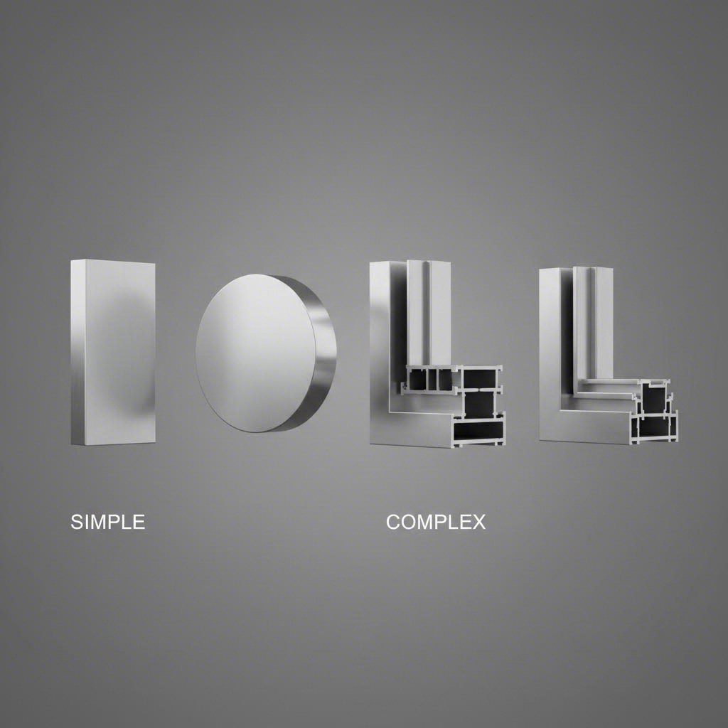
Now here's the nuance that separates aluminum extrusion design experts from novices: profile geometry directly determines what tolerances are actually achievable.
Think about what happens during extrusion. Heated aluminum billet gets forced through a die opening at tremendous pressure. Simple, symmetrical shapes allow material to flow evenly—pressure distributes uniformly, cooling rates stay consistent, and the resulting profile holds dimensions predictably.
Complex shapes? That's another story entirely.
Consider a multi-hollow profile with varying wall thicknesses, deep channels, and asymmetrical features. Material flows differently through thin sections versus thick ones. Narrow tongues in the die deflect under pressure. Thin walls cool faster than thick sections, creating internal stresses that cause warping. The physics simply don't permit the same precision as a basic rectangular bar.
The Aluminum Association tolerance tables account for this through "space dimension" tolerances that increase based on distance from solid metal. For dimensions where more than 25% is open space (like across a channel or hollow section), tolerances widen progressively:
What does this mean practically? If your aluminum extrusion design includes a 3-inch-deep channel, the tolerance at the channel opening will be larger than at the base. A dimension that's ±0.014 inches at the profile base might be ±0.026 inches at a position 2 inches into the channel.
Smart designers work with these realities rather than against them. Position critical mating surfaces on solid sections. Avoid placing precision fit features deep within channels. Design wall thicknesses as uniformly as possible to minimize differential cooling. These decisions during aluminum extrusion design prevent tolerance headaches during production.
The aluminum alloy you choose isn't just about strength, corrosion resistance, or surface finish—it directly affects achievable tolerances. This is where even experienced engineers sometimes get tripped up.
Softer alloys extrude more easily. Alloy 6063, the most common architectural aluminum, flows readily through dies because of its lower flow stress at extrusion temperatures. This easier flow means more consistent material distribution and, consequently, tighter achievable tolerances. When precision matters most, 6063-T5 or 6063-T6 tempers often deliver the best dimensional control.
Harder alloys present more challenges. Alloy 6061 offers higher strength than 6063 but requires greater extrusion pressure. This additional force can cause die deflection, particularly on thin-wall features. The result? Standard aluminium extrusions in 6061 may show slightly more dimensional variation than equivalent 6063 profiles.
The tolerance tables in ANSI H35.2 actually account for alloy differences. Note the footnotes referencing "5XXX alloys with magnesium content greater than or equal to 4.0% nominal"—these require 150% of standard tolerance values. Alloys like 5083 and 5086, common in marine applications, are harder to control dimensionally than the 6000-series workhorse alloys.
Temper also matters. Stress-relieved tempers (T3510, T4510, T6510, T73510, T76510, T8510) have special tolerance considerations that "shall be as agreed upon between purchaser and vendor at the time the contract or order is entered." If you're specifying these tempers, expect a tolerance discussion with your supplier rather than simply referencing standard tables.
The takeaway? Match your alloy selection to both performance requirements and tolerance needs. If dimensional precision is paramount but ultra-high strength isn't required, a 6063 profile might outperform a 6061 alternative—not in load capacity, but in consistency and fit.
With this understanding of how tolerance classes, profile complexity, and alloy selection interact, you're equipped to make specification decisions that balance performance against cost. Next, we'll explore exactly how those tolerance choices translate into dollars—and when tighter specifications truly justify their premium.
Here's the uncomfortable truth most aluminum extrusion design guides don't tell you: that precision tolerance you just specified might have doubled your part cost without adding functional value. Understanding the cost-tolerance relationship separates engineers who deliver projects on budget from those constantly explaining overruns.
The relationship between tolerance tightness and manufacturing cost isn't linear—it's exponential. According to manufacturing research, moving from standard tolerances to precision specifications can increase costs by 2x or more, while ultra-precision requirements can push costs 24 times higher than baseline. Let's explore why this happens and how to make smarter specification decisions.
When you specify tolerances tighter than standard, you're not just requesting smaller numbers on an inspection report. You're fundamentally changing how parts must be manufactured, inspected, and validated.
Consider what happens behind the scenes. A standard extrusion runs at optimal press speeds through a die designed for normal production pressures. Tighten the tolerance requirements, and suddenly the manufacturer must slow the extrusion speed to maintain dimensional control. Die adjustments become more frequent. Temperature monitoring intensifies. Quality checks that previously sampled one piece per hundred now examine every tenth part—or every single piece.
The hidden costs extend even further. Temperature-controlled manufacturing environments become necessary for the tightest specifications. Specialized inspection equipment replaces standard tools. Documentation requirements multiply. Even material handling changes—parts that could previously stack for transport now require individual protection to prevent damage affecting critical dimensions.
Here's what surprises many engineers: standard tolerances published in aluminum extrusion design guidelines handle the vast majority of applications perfectly well. The Aluminum Association didn't establish these values arbitrarily—they represent decades of manufacturing experience balancing capability with cost-effectiveness.
Standard tolerances typically work when:
Think about a typical architectural curtain wall application. Extruded mullions connect through gaskets and sealants designed to accommodate dimensional variation. The glazing system includes adjustment mechanisms. Standard tolerances per aluminium extrusion design guidelines deliver perfectly functional assemblies at baseline cost.
Contrast this with a precision optical mount where component positions must align within microns. Here, extrusion tolerances alone won't suffice regardless of class—secondary machining establishes the final critical dimensions. Specifying precision extrusion tolerances on features destined for machining adds cost without functional benefit.
The most expensive tolerance is the one that provides no functional benefit. Smart specification requires asking: what actually matters for this part's function?
Start with tolerance stack-up analysis. When your assembly combines multiple extrusions, variations accumulate. Three parts each at ±0.010 inches can stack to ±0.030 inches total variation at the assembly level. Understanding this accumulation helps you decide where tight control delivers value versus where it merely adds cost.
Consider this decision framework:
| Design Scenario | Recommended Approach | Rationale |
|---|---|---|
| Sliding or press-fit interfaces | Precision tolerances on mating dimensions only | Functional fit requires controlled clearance; other dimensions non-critical |
| Bolted structural connections | Standard tolerances with adequate hole clearance | Bolt clearance accommodates tolerance stack-up naturally |
| Heat sink mounting surfaces | Precision flatness; standard other dimensions | Thermal transfer depends on surface contact, not overall size |
| Machined interface locations | Standard extrusion tolerances with machining allowance | Secondary operations establish final precision; extrusion tolerance irrelevant |
| Visible architectural joints | Precision on mating edges; standard elsewhere | Visual alignment matters at joints; hidden surfaces don't affect aesthetics |
From the manufacturer's perspective, early communication matters enormously. Experienced extrusion partners can often suggest design modifications that achieve your functional requirements with more achievable tolerances. A slight geometry change, a relocated datum surface, or an adjusted wall ratio might eliminate the need for precision specifications entirely.
The aluminum extrusion design guide principle here is straightforward: specify what you truly need, not what feels professionally conservative. Over-tolerance stems from uncertainty—when designers aren't sure what matters, they tighten everything "just in case." That uncertainty costs real money without adding real value.
When precision truly matters, invest in tolerance analysis before specifying. Calculate stack-ups. Identify functional interfaces. Determine which dimensions actually control performance. Then specify precision only where the math demonstrates necessity.
With cost implications clear, you're ready to learn the practical mechanics of communicating tolerance requirements to suppliers—including the specification mistakes that cause the most project delays and how to avoid them.
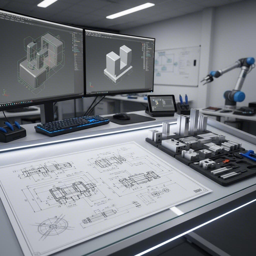
You understand tolerance classifications and cost implications—but how do you actually communicate these requirements to manufacturers? This is where theory meets reality, and where many projects encounter their first serious delays.
The gap between design intent and manufacturing execution often traces back to specification documents. Unclear drawings, missing information, and poorly communicated priorities force suppliers to guess—or worse, to quote conservatively and charge premium prices for uncertainty. Let's fix that with practical guidance you can apply immediately.
Your engineering drawing is the primary communication tool between your design and the shop floor. For aluminum extrusion bars, tubes, and custom profiles alike, certain elements must appear clearly and consistently.
Before diving into individual callouts, understand that manufacturers reference different documentation depending on your order type. When selecting from stock aluminum extrusion profiles or standard catalog shapes, published specifications typically govern tolerances automatically. Custom profiles require explicit documentation—and that's where precision in your drawings pays dividends.
For GD&T applications, be aware that extrusion terminology differs from machining conventions. As industry experts note, standard extrusion "flatness" refers to cross-sectional flatness of the profile, while "straightness" describes bow along the length—different from how machinists typically interpret these terms. Clarify your intent explicitly when using geometric tolerancing on extrusion drawings.
After reviewing thousands of customer drawings, manufacturers consistently identify the same specification errors. Avoiding these pitfalls saves time, reduces quote iterations, and prevents production surprises.
Mistake #1: Defaulting to title block tolerances. When pressed for time, engineers often apply blanket tight tolerances via title block specifications. This approach—while expedient—frequently results in extruders declining to quote or pricing parts excessively. Worse, it can trigger requests for print deviations, extended setups, costly die trials, and ultimately delayed deliveries.
Mistake #2: Over-tolerancing non-critical features. Adding tight tolerances on dimensions that don't affect form, fit, or function represents one of the largest sources of hidden cost. Some features may not require numerical tolerances at all—a visual inspection confirming the intended shape suffices.
Mistake #3: Ignoring manufacturability in tolerance placement. Consider a part with acceptable saw-cut tolerances but machined features dimensioned from both ends. This seemingly reasonable approach can force additional milling operations, multiple clamping setups, or touch-probing operations that dramatically increase costs.
Mistake #4: Specifying tolerances without capability discussion. Tolerances are affected by press size, billet temperature, extrusion speed, die design, cooling time, stretch amount, and ambient conditions. Specifying tighter values than the process can achieve guarantees frustration. Per manufacturing guidance, discussing tight tolerance features with your extruder during the design and quoting stage is essential for mutual agreement.
Mistake #5: Neglecting CpK requirements. Establishing process capability (CpK) values is critical for dimensional tolerances. A 1.33 CpK requirement effectively reduces the usable tolerance band to 75 percent. Requiring 1.67 CpK shrinks it to 60 percent. Verify your extruder's ability to control their processes to your specified CpK values before production begins.
Mistake #6: Missing identification marks on symmetrical profiles. When designing symmetrical shapes, add an identification mark to allow proper orientation during fabrication and assembly. This reduces tolerance variance characteristic of the extrusion process.
Beyond the drawing itself, effective communication with your manufacturing partner determines project success. Whether you're ordering aluminum bar extrusions, architectural shapes, or complex custom profiles, certain practices streamline the quoting and production process.
Engage early in the design process. An experienced extruder provides valuable feedback on manufacturability before you finalize drawings. This collaboration prevents costly redesigns and production delays. Many manufacturers offer design-for-manufacturing reviews at no charge during the quoting phase.
Prioritize your tolerance requirements explicitly. Not all dimensions carry equal importance. When submitting drawings, include a tolerance hierarchy identifying which specifications are absolutely critical versus which have flexibility. This transparency helps manufacturers focus quality control efforts where they matter most—potentially reducing your costs.
Discuss capability before specifying. Some extruders can hold tighter tolerances than published standards. Others may struggle with values that competitors achieve routinely. Having capability conversations during quoting prevents unpleasant surprises during production. Request capability studies for critical dimensions if your CpK requirements are stringent.
Address imperial and metric clearly for international projects. If your drawing uses metric dimensions but references ANSI H35.2 (an imperial-based standard), confusion is inevitable. Similarly, specifying EN 755-9 tolerances on inch-dimensioned drawings creates interpretation challenges. Match your dimensioning system to your tolerance standard, or provide explicit conversion notes.
When browsing an aluminum extrusion catalog or extruded aluminum shapes catalog, remember that stock profiles carry their own published tolerances. Custom modifications to standard shapes may require updated tolerance agreements. If you're modifying stock aluminum extrusion profiles with secondary operations, clarify which tolerances apply to the as-extruded condition versus post-machining dimensions.
Which dimensions deserve the most attention? Focus tolerance control on:
Conversely, dimensions that typically don't require tight control include internal features hidden in assembly, non-mating external surfaces, and any dimension destined for machining where the secondary operation establishes final precision.
The bottom line? Your specification documents are a conversation starter, not a dictate. The best outcomes emerge when designers and manufacturers collaborate to balance functional requirements against manufacturing realities—ideally before production begins rather than after the first shipment arrives out of spec.
With specification fundamentals established, you're ready to explore how different applications—structural, architectural, precision mechanical—prioritize tolerance requirements differently, and how surface treatments affect your final dimensions.
You've mastered tolerance specifications and communication strategies—but here's what catches even experienced engineers off guard: the same dimensional tolerance that works perfectly for one application can cause assembly failures in another. Different industries prioritize different tolerance categories, and understanding these application-specific requirements prevents costly specification mismatches.
Whether you're designing aluminum tube profiles for fluid systems, architectural aluminum extrusions for building facades, or precision components for industrial machinery, your tolerance priorities should align with how the part actually functions. Let's explore what matters most across common application categories.
Structural aluminium extrusions carry loads, resist forces, and maintain integrity under stress. For these applications, certain tolerance categories matter far more than others.
Consider a structural I-beam supporting building loads. Does it matter if the overall height varies by ±0.015 inches? Rarely—structural calculations include safety factors that accommodate standard dimensional variation. However, web thickness consistency directly affects load-bearing capacity. A web specified at 0.250 inches that varies between 0.225 and 0.275 inches across its length could create unpredictable structural behavior.
For aluminum tube profiles used in framing or structural applications, wall thickness uniformity typically represents the most critical tolerance. According to industry standards, wall thickness tolerances of ±10% apply to standard production. Structural engineers designing to allowable stress limits must account for this variation—or specify tighter tolerances when minimum wall thickness is critical to safety factors.
Straightness tolerance becomes paramount for long structural members. A 20-foot column with excessive bow creates eccentric loading that amplifies stress concentrations. Standard straightness of 0.0125 inches per foot works for most applications, but heavily loaded columns or precision-fit structural systems may require tighter control.
Architectural aluminum extrusions serve a fundamentally different purpose than structural members. Yes, curtain wall mullions carry wind loads—but their primary function involves creating weather-tight enclosures with consistent visual appearance across hundreds or thousands of linear feet.
What tolerances matter most? Think about what the eye notices. Adjacent aluminum panel extrusions with misaligned faces create visible shadows and reveal lines. Mullion covers that don't quite fit their base profiles look unprofessional. Glazing pocket dimensions that vary cause inconsistent sightlines across a facade.
For architectural applications, flatness and angularity often matter more than raw dimensional accuracy. A mullion cover slightly narrower than nominal might function perfectly—but if its visible face isn't flat, light catches the undulation and reveals the imperfection. Similarly, a 90-degree corner that measures 89 degrees creates visible misalignment where profiles meet.
Color matching across anodized or painted profiles also demands dimensional consistency. Anodizing produces color through interference effects related to oxide layer thickness. Profiles with varying wall thicknesses may develop slightly different oxide characteristics during the anodizing process, potentially creating visible color variation in matching components.
Here's where many tolerance specifications go wrong: engineers dimension their drawings for final assembly but forget that surface treatments add measurable thickness. That precision fit you calculated? It might become an interference fit after anodizing—or develop excessive clearance after accounting for coating buildup.
According to surface treatment guidance, anodizing creates an aluminum oxide layer that's integral to the base metal. This layer grows both outward and inward from the original surface:
Powder coating adds substantially more thickness. The electrostatic process deposits dry powder that melts and flows during oven curing, creating film builds typically ranging from 0.002 to 0.004 inches. Premium architectural coatings may exceed 0.004 inches for enhanced durability.
What does this mean practically? For a sliding fit between mating extrusions designed with 0.005-inch total clearance, hard anodizing both components could consume 0.004 to 0.006 inches of that clearance—potentially creating an interference condition. Powder coating would definitely eliminate the clearance and require post-coating machining.
For threads and tapped holes, the situation demands particular attention. As industry experts note, masking threads before powder coating prevents coating buildup that affects thread engagement. For anodizing, specify fit classes that accommodate oxide growth, or plan for post-anodizing tap operations to restore thread dimensions.
| Application Type | Critical Tolerances | Typical Class | Surface Treatment Considerations |
|---|---|---|---|
| Structural | Wall thickness, straightness | Standard | Coatings rarely affect structural function; standard finishes acceptable |
| Architectural | Flatness, angularity, visible surface dimensions | Standard to Precision on visible features | Coating uniformity affects appearance; specify consistent film build |
| Precision Mechanical | Mating dimensions, locating features, bore diameters | Precision or Custom | Account for coating thickness in tolerance stack-up; mask or post-machine critical surfaces |
| Fluid Handling (tubes) | Wall thickness, ID concentricity, surface finish | Standard to Precision | Internal surfaces may require masking; anodize affects flow characteristics |
| Electrical/Thermal | Flatness for contact surfaces, mounting feature locations | Precision on contact areas | Anodizing insulates—mask grounding points; coating thickness affects thermal transfer |
The lesson here? Specify dimensions for the condition that matters for function. If your assembly requires specific clearances after finishing, dimension accordingly—either specifying pre-treatment dimensions with coating allowance notes, or post-treatment dimensions with manufacturing instructions to account for coating buildup.
For applications requiring both precision fits and corrosion protection, consider a duplex system combining anodizing with powder coating. While this delivers outstanding durability, it also adds the combined thickness of both treatments. Alternatively, mask critical surfaces during coating and accept reduced corrosion protection in those areas, or plan for precision machining after coating to restore critical dimensions.
Understanding these application-specific considerations helps you specify tolerances that actually matter for your project's success. But achieving those tolerances consistently requires the right manufacturing partner—with appropriate equipment, quality systems, and expertise to deliver what you've specified.

You've specified your tolerances correctly, selected appropriate tolerance classes, and documented everything clearly on your drawings. Now comes the critical question: can your manufacturing partner actually deliver what you've specified?
The gap between tolerance specifications and real-world manufacturing capability catches many engineers off guard. A supplier might accept your purchase order without hesitation—only to deliver parts that require rework, delays, or costly rejections. Understanding what separates capable extrusion partners from marginal ones helps you select suppliers who deliver consistent results, not excuses.
Think of the extrusion die as the heart of the entire process. From the moment heated aluminum enters the die chamber until it exits the die lips, everything happening in those few seconds determines whether your tolerances are achievable. As die manufacturing experts explain, the flow channel design within the die chamber spreads aluminum to the desired width while achieving uniform thickness—and this is where tolerance capability begins.
What makes die design so critical for your aluminium extrusion tube or aluminum extrusion bar projects? Consider these factors:
Press capabilities matter just as much. Matching profile requirements to appropriate press tonnage ensures adequate force for consistent material flow without die deflection. When manufacturers operate presses near their capacity limits, dimensional control suffers. Conversely, an oversized press for a small profile wastes energy but maintains excellent control.
According to precision manufacturing guidance, precise control of billet temperature, ram speed, exit temperature, and cooling rate is essential. Operators must continuously monitor these parameters to maintain surface quality, consistent dimensions, and acceptable mechanical properties. Real-time monitoring helps identify deviations before they affect finished products.
For aluminium extruded tubes and complex profiles, manufacturers with multiple press sizes can match each job to optimal equipment. A facility operating presses ranging from 600T to 5500T, for example, can select the ideal tonnage for your specific profile geometry—whether that's a delicate precision tube or a heavy structural section.
Achieving tight tolerances means nothing if you can't verify them consistently. Quality control systems separate reliable suppliers from those who deliver uncertainty with every shipment.
What should you expect from a capable extrusion partner? Start with inspection equipment. As industry leaders note, precision measurement tools like optical measurement machines and coordinate measuring machines (CMM) provide micron-level accuracy. Traditional tools—calipers and micrometers—remain valuable for routine checks, but complex profiles and tight tolerances demand advanced measurement capability.
Quality systems extend beyond equipment. Look for manufacturers with recognized certifications like AS9100 for aerospace applications or ISO 9001 for general quality management. These certifications indicate proactive approaches to identifying defects and minimizing risks throughout the manufacturing process.
Per manufacturing best practices, critical quality control elements include:
For die manufacturing quality specifically, precision requirements demand inspection at every stage. CNC machining requires verification of at least twenty different dimensions and tolerances. Electroplating thickness must be measured using coating thickness gauges to ensure specifications are met. Surface roughness verification using precision instruments confirms post-plating polishing achieves required smoothness—typically Ra 0.03-0.04 µm for standard extrusion dies.
When evaluating potential suppliers for your precision extrusion projects, certain capabilities signal genuine manufacturing competence versus aspirational claims. Here's what to assess:
Equipment range and flexibility: Manufacturers with diverse press tonnages can match your profile to optimal equipment. A comprehensive facility—like Shengxin Aluminium's 35 extrusion presses spanning 600T to 5500T—offers flexibility for everything from delicate precision profiles to heavy structural sections. This range means your job runs on appropriate equipment rather than being forced onto whatever press happens to be available.
Secondary processing capabilities: Some tolerances simply cannot be achieved through extrusion alone. When your specifications require precision beyond as-extruded capability, deep processing operations like CNC machining for precise cutting, drilling, and bending become essential. Manufacturers with integrated machining centers deliver finished components ready for assembly—eliminating coordination between multiple suppliers and reducing tolerance stack-up between operations.
Surface treatment options: As discussed in application-specific requirements, coatings affect final dimensions. Partners offering comprehensive surface treatments—anodizing in custom colors, powder coating, PVDF, and specialty processes—can manage the entire finishing sequence while maintaining dimensional control. This integration prevents the handoff errors that occur when extrusions transfer between independent finishing houses.
Technical support depth: According to the aluminium extrusion design guide principles covered earlier, early engagement with manufacturing partners prevents costly redesigns. Look for suppliers whose technical teams participate actively in design reviews, offering feedback on manufacturability and tolerance achievability before you finalize specifications.
Experience with your application type: A manufacturer producing predominantly architectural extrusions may lack the process controls and inspection protocols required for precision mechanical components. Ask specifically about experience with applications similar to yours—and request references from customers with comparable tolerance requirements.
Questions to ask potential suppliers:
The right manufacturing partner doesn't just accept your tolerance specifications—they help you optimize them. Experienced extruders suggest design modifications that achieve functional requirements with more manufacturable tolerances. They identify potential issues during quoting rather than during production. They communicate proactively when process variations might affect critical dimensions.
With manufacturing partnership fundamentals established, you're ready to synthesize everything you've learned into actionable next steps for your precision extrusion projects.
You've journeyed through the complete landscape of aluminum extrusion standard tolerances—from foundational concepts through industry standards, tolerance categories, classification systems, cost implications, specification techniques, and application-specific requirements. That's substantial ground to cover. But knowledge without action remains theoretical.
The real question now? How do you translate everything you've learned into successful projects that arrive on time, within budget, and ready for assembly? Let's distill the critical insights and map your path forward.
Think back to the core principles woven throughout this guide. Several themes emerged repeatedly—because they represent where projects succeed or stumble.
Tolerance classification drives cost and capability. Standard tolerances per Aluminum Association tables handle most applications effectively at baseline cost. Precision tolerances—approximately 65-70% of standard values—add 10-25% to part costs but deliver tighter dimensional control for critical interfaces. Custom tolerances beyond published tables require capability discussions and often secondary machining, pushing costs significantly higher.
Profile geometry determines achievable precision. Simple, symmetrical shapes hold tighter tolerances than complex multi-hollow profiles. Wall thickness uniformity, circumscribing circle diameter, and feature depth all influence what's physically possible during extrusion. Designing with these manufacturing realities—rather than fighting against them—prevents specification frustration.
Alloy selection affects more than mechanical properties. Softer alloys like 6063 extrude more consistently than harder alloys like 6061 or high-magnesium 5000-series materials. When dimensional precision matters most, alloy choice becomes a tolerance decision as much as a strength decision.
Surface treatments change final dimensions. Standard anodizing adds 0.0002-0.0004 inches per surface. Hard anodizing builds 0.001-0.003 inches. Powder coating deposits 0.002-0.004 inches or more. Specifying tolerances without accounting for these additions creates assembly problems. Dimension for the condition that matters—either pre-treatment with coating allowances or post-treatment with manufacturing adjustments.
Early manufacturer engagement prevents costly surprises. According to design optimization research, discussing tight tolerance features with your extruder during the design and quoting stage is essential for mutual agreement on achievability. Capability conversations before production prevent unpleasant discoveries after parts arrive.
The most expensive tolerance is the one that provides no functional benefit—specify what you truly need, not what feels professionally conservative.
Ready to apply these principles? Whether you're developing new custom profiles or refining specifications for existing projects, this checklist guides your tolerance specification process:
When evaluating stock aluminium extrusion profiles versus custom designs, remember that standard catalog shapes carry published tolerances automatically. Custom modifications or tighter specifications require explicit documentation and supplier capability verification.
For projects requiring precision aluminum solutions with specific tolerance requirements, partnering with experienced manufacturers who offer end-to-end support—from die development through mass production—eliminates coordination gaps between design intent and manufacturing reality. Suppliers with comprehensive capabilities integrate extrusion, deep processing operations, and surface treatments under unified quality control, ensuring tolerances are maintained throughout the entire production sequence.
Shengxin Aluminium's 30+ years of industry experience exemplifies this integrated approach. With 35 extrusion presses spanning 600T to 5500T, CNC machining centers for precise secondary operations, and comprehensive surface treatment options including custom-color anodizing and PVDF coatings, their technical team provides the end-to-end support that transforms tolerance specifications into consistently conforming parts. For engineers ready to discuss specific tolerance requirements, their factory-direct pricing and design consultation services offer a practical path from concept to production.
The aluminum extrusion industry continues evolving—tighter achievable tolerances, more sophisticated quality systems, greater integration between extrusion and finishing operations. But the fundamentals covered in this guide remain constant: understand what matters functionally, specify appropriately for your application, communicate clearly with manufacturing partners, and verify capability before committing to production.
Your next project deserves tolerance specifications that work—the first time. Apply these principles, and you'll join the engineers who get tolerance specifications right rather than those still learning from costly mistakes.
Standard tolerances for aluminum extrusions are defined by ANSI H35.2 and Aluminum Association Tables 11.5-11.14. Linear cross-sectional tolerances are typically ±0.008 inches per inch of dimension, wall thickness tolerances are ±10% of specified thickness, and straightness tolerance is 0.0125 inches per foot of length. These baseline values apply to most general-purpose applications without additional cost premiums.
Precision tolerances are approximately 65-70% tighter than standard values. For example, a cross-sectional dimension with ±0.008 inch standard tolerance would have ±0.005 inch precision tolerance. Precision specifications require enhanced process controls, slower extrusion speeds, and more rigorous inspection, typically adding 10-25% to part costs and potentially extending lead times by 1-2 weeks for die optimization.
Profile complexity directly impacts achievable tolerances. Simple, symmetrical shapes allow even material flow and consistent cooling, enabling tighter dimensional control. Complex multi-hollow profiles with varying wall thicknesses experience uneven pressure distribution and differential cooling, requiring wider tolerances. Space dimensions across channels or hollow sections need progressively larger tolerances the deeper they extend from solid metal sections.
Surface treatments add measurable thickness that must be factored into tolerance specifications. Standard anodizing adds 0.0002-0.0004 inches per surface, architectural anodizing builds 0.0004-0.0007 inches, hard anodizing creates 0.001-0.003 inches, and powder coating deposits 0.002-0.004 inches or more. Engineers should specify dimensions for either pre-treatment or post-treatment conditions, with appropriate allowances noted on drawings.
The primary standards include ANSI H35.2 for dimensional tolerances of aluminum mill products in North America, ASTM B221 for complete specifications of extruded bars, rods, wire, profiles and tubes, and EN 755-9 for European metric specifications. Aerospace applications often require additional AMS specifications like AMS-QQ-A-225/8 or AMS-QQ-A-200/3 that build upon ASTM standards with stricter controls.



 online service
 0086 136 3563 2360
 sales@sxalu.com
 +86 136 3563 2360
 English
 français
 Deutsch
 русский
 español
 português
 العربية
 ไทย
ไทย Việt
Việt Українська