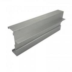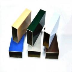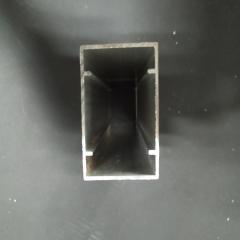
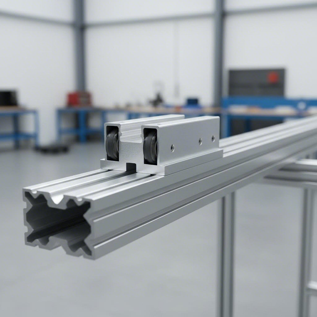
Ever wondered how CNC machines, 3D printers, and automated assembly lines achieve such precise, repeatable movement? The answer often lies in a deceptively simple technology: linear motion aluminum extrusion. At its core, this system consists of specially designed aluminum profiles that guide components along a single axis with remarkable smoothness and accuracy.
Think of it like a high-performance train track system. The extruded aluminum rails provide the pathway, while bearing or wheel assemblies act as the train cars gliding effortlessly along that path. This combination delivers controlled, predictable motion that engineers and makers rely on for everything from hobby projects to industrial automation.
Linear motion aluminum extrusion operates on a straightforward principle: constrain movement to one direction while minimizing friction and maintaining rigidity. When you push a standard object across a surface, it can drift, wobble, or require significant force to move. A properly designed linear rail eliminates these problems entirely.
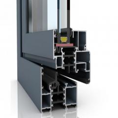
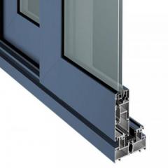
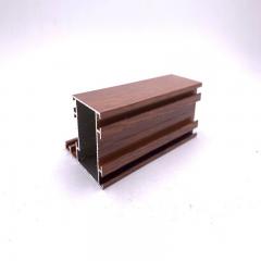
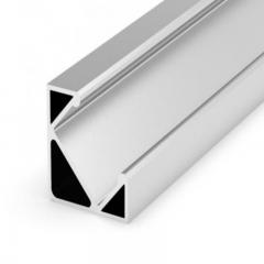
The aluminum extrusion rail serves as the structural backbone of this system. Manufacturers create these profiles by forcing heated aluminum through precision-shaped dies, producing consistent cross-sections with tight tolerances. The resulting rail alu profiles feature carefully engineered grooves or tracks that interface with rolling elements, whether wheels, ball bearings, or roller assemblies.
What makes this approach so effective? The geometry of the extrusion rail creates multiple contact points between the moving carriage and the stationary rail. These contact points distribute loads evenly, reduce wear, and maintain alignment even under stress. You'll notice that quality extruded aluminum rails exhibit minimal deflection, meaning your motion system stays accurate throughout its operational life.
Understanding how these systems work requires breaking them down into their essential elements. Every functional linear motion setup depends on three interconnected components working in harmony:
When these three elements work together correctly, you get a motion system capable of positioning accuracy measured in hundredths of a millimeter. The beauty of aluminum-based systems lies in their accessibility. Unlike hardened steel linear guides that require specialized knowledge and expensive components, extruded aluminum rails offer an approachable entry point without sacrificing fundamental performance.
Now that you understand the fundamental components of linear motion systems, you're probably asking yourself: which profile type should I actually use? The v slot vs t slot debate sits at the heart of countless project planning sessions, and choosing incorrectly can mean rebuilding your entire system later. Let's break down what makes these profiles different and when each one truly shines.
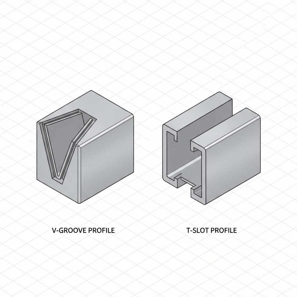
Imagine cutting through each profile and examining the cross-section. That's where the real story begins. V slot extrusion features distinctive angled grooves, typically cut at 45-degree angles, running along one or more faces of the profile. These V-shaped channels aren't just decorative; they're engineered specifically to accept V-wheels that ride directly in the groove. The wheel's beveled edge nests perfectly into the vslot channel, creating a self-centering contact point that guides motion with surprising precision.
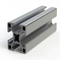
T-slot profiles take a fundamentally different approach. Their perpendicular channels, shaped like the letter T when viewed in cross-section, were originally designed for modular framing connections. The open slot configuration accepts T-nuts and bolt heads for flexible mounting anywhere along the rail length. When you need linear motion with t slotted rails, you'll typically mount separate linear bearing systems alongside or on top of the profile rather than using the slot itself for guidance.
Here's what this means practically: with V-slot, your linear motion capability is built into the profile geometry. With T-slot, you're adding linear motion components to a general-purpose framing system. Neither approach is inherently superior; they simply solve different problems.
Choosing between these profiles comes down to matching their strengths to your specific requirements. V-slot systems excel when you want integrated simplicity. A single piece of aluminum serves as both your structural frame and your motion guide. This reduces part count, simplifies assembly, and often lowers overall cost for motion-focused applications like 3D printer axes or camera sliders.
T-slot profiles dominate when versatility matters most. Need to mount sensors, brackets, or accessories at arbitrary positions? The open slot design accommodates changes without drilling or machining. Industrial applications favor t slot vs v slot options when machines require frequent reconfiguration or when structural framing takes priority over integrated motion.
Consider your load requirements carefully. V-wheels riding in grooves handle moderate loads effectively but can show wear under heavy continuous use. Systems requiring higher precision or heavier payloads often pair T-slot frames with dedicated linear rail components, separating structural and motion functions for optimized performance in each role.
| Characteristic | V-Slot Profile | T-Slot Profile |
|---|---|---|
| Profile Geometry | 45-degree angled V-grooves on faces | Perpendicular T-shaped channels |
| Compatible Bearing Types | V-wheels (Delrin, polycarbonate) roll directly in grooves | Requires separate linear bearings, rails, or wheel plates |
| Typical Applications | 3D printers, CNC routers, laser cutters, camera motion rigs | Machine frames, workstations, enclosures, industrial automation structures |
| Load Characteristics | Moderate loads; wheel contact area limits heavy-duty use | Scalable based on added linear components; handles heavy loads when paired with proper bearings |
| Ease of Assembly | Simpler for motion systems; fewer separate components needed | More flexible mounting options; easier accessory attachment |
| Cost Efficiency | Lower total cost for integrated motion applications | Lower initial profile cost; additional linear components add expense |
| Precision Potential | Good for hobby and semi-professional use; wheel adjustment affects accuracy | Higher precision possible with quality linear bearing additions |
One practical consideration often overlooked: hybrid approaches work beautifully. Many builders use V-slot for motion axes while incorporating standard T-slot for non-moving structural elements. This strategy captures the best of both worlds without forcing compromises where they matter most.
Understanding these geometric and functional differences prepares you for the next critical decision: selecting the right bearing type to pair with your chosen profile.
So you've selected your profile type. Now comes the question that truly determines how your system performs: which bearing approach will carry your payload along that aluminum rail? This decision affects everything from positioning accuracy to maintenance schedules to long-term reliability. Yet surprisingly, most resources simply list product options without explaining why you'd choose one over another.
Three primary bearing technologies dominate v slot linear rail and aluminum extrusion applications. Each brings distinct advantages and limitations that make it ideal for specific situations. Understanding these trade-offs transforms you from someone guessing at components to an engineer making informed decisions.
When you examine a linear rail v slot setup on a typical 3D printer or hobby CNC machine, you'll likely spot V-wheels doing the heavy lifting. These deceptively simple components consist of precision-machined wheels with beveled edges that nest into the V-groove rail profile. The wheel material, typically Delrin (acetal resin) or polycarbonate, rolls smoothly against the aluminum with minimal friction.
Why do so many builders gravitate toward this approach? The answer lies in accessibility and simplicity. V-wheel systems require no lubrication, generate minimal noise, and allow straightforward adjustment through eccentric spacers. When a wheel wears out, replacement takes minutes and costs very little.
V slot aluminium extrusion paired with quality wheels delivers surprisingly good performance for the investment. According to testing in 3D printer applications, Delrin wheels provide sufficient accuracy for most hobbyist and semi-professional work while operating quietly enough for home environments.
When your project demands tighter tolerances or heavier loads than V-wheels can handle, linear ball bearings enter the picture. These sophisticated components use recirculating steel balls running in hardened raceways to achieve remarkably smooth, precise motion. The aluminum extrusion slider block travels along a matching rail profile with positioning accuracy that can reach hundredths of a millimeter.
The engineering behind recirculating ball systems is elegant. As the carriage moves, steel balls roll between the carriage and rail surfaces, then circulate back through internal channels to repeat the cycle. This design minimizes friction while distributing loads across many contact points simultaneously.
Aluminium v slot extrusion users sometimes mount separate linear rail assemblies alongside their profiles, gaining the structural benefits of aluminum framing with the precision of dedicated ball bearing guides. This hybrid approach appears frequently in professional-grade CNC routers and laser cutters where accuracy directly impacts output quality.
What happens when even ball bearings aren't enough? V groove rail applications involving extremely heavy loads or demanding industrial environments often turn to roller bearing systems. Instead of small recirculating balls, these guides use cylindrical rollers that provide dramatically increased contact area with the rail surface.
Imagine the difference between rolling a marble versus rolling a cylinder across a surface. The cylinder contacts more material, distributing force more effectively. This same principle allows roller systems to handle loads that would quickly overwhelm ball bearing alternatives. Industrial automation, heavy CNC machinery, and large-format manufacturing equipment frequently rely on roller-based linear guides.
The trade-off? Roller systems cost more, weigh more, and require more robust mounting structures. They represent the heavy artillery of linear motion, deployed when nothing else can handle the job.
Selecting your bearing type ultimately comes down to honest assessment of your requirements. Building a desktop 3D printer? V-wheels will likely serve you perfectly. Designing a production CNC machine that runs multiple shifts? Ball bearings or roller systems justify their premium. The key is matching capability to need rather than defaulting to the cheapest or most expensive option available. With your bearing decision made, the next consideration becomes profile sizing, where the relationship between extrusion dimensions and load capacity determines whether your system performs reliably or struggles under stress.
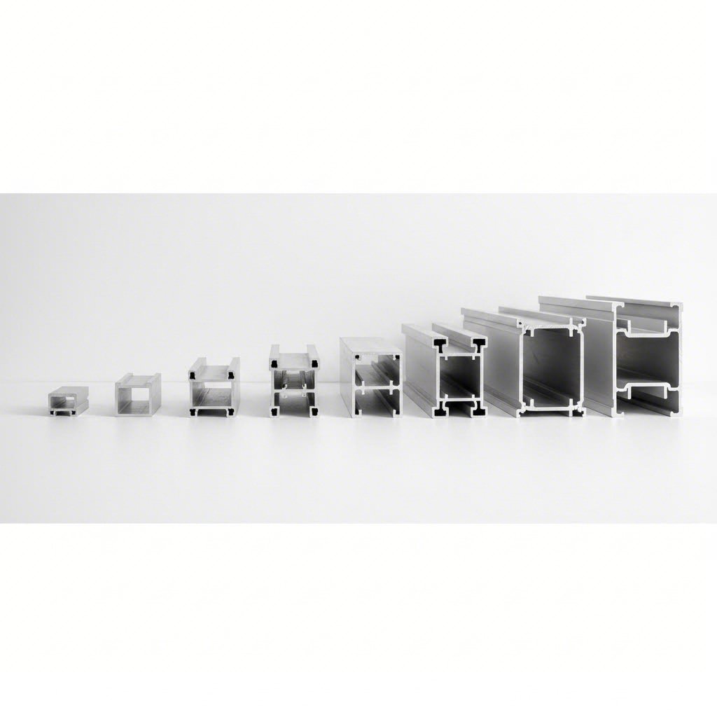
You've chosen your profile type and bearing system. Now comes a question that trips up even experienced builders: what size extrusion do you actually need? Walk through any supplier catalog and you'll encounter designations like 2020, 2040, or 4080 without much explanation of what these numbers mean for your project. Understanding the relationship between profile dimensions and linear motion performance transforms random number selection into confident engineering decisions.
Think of profile sizing like choosing lumber for a construction project. A 2x4 works fine for a shelf bracket, but you wouldn't use it as a main support beam for a deck. The same logic applies to extruded aluminum rail selection. Undersizing leads to deflection, vibration, and positioning errors. Oversizing wastes money and adds unnecessary weight. Finding the sweet spot requires understanding how series designations translate to real-world capability.
The numbering system for aluminum extrusion profiles follows a logical pattern once you crack the code. A 1010 aluminum rail measures approximately 10mm x 10mm in cross-section. A 2040 slot rail spans 20mm x 40mm. The first two digits typically indicate width, while the second pair indicates height. Simple enough, but what do these dimensions actually mean for your linear motion system?
Cross-sectional area directly correlates with rigidity and load-bearing capability. When you double the profile width, you don't just double the strength; you dramatically increase the moment of inertia, which determines resistance to bending. This explains why a slotted rail measuring 40mm x 40mm handles loads far exceeding twice what a 20mm x 20mm profile manages.
For linear motion applications, deflection matters enormously. Imagine a gantry-style CNC router with the cutting head traveling along an unsupported span. If the rail sags even slightly under the weight of the spindle motor, your cuts will curve instead of staying flat. Longer spans demand stiffer profiles, which means stepping up in series size or adding intermediate supports.
The 10 series profiles work well for lightweight applications with short travel distances. Desktop 3D printers and small laser engravers commonly use these compact extrusions where space constraints outweigh load requirements. Moving to 20 series profiles opens up mid-range possibilities: larger 3D printers, hobby CNC machines, and camera motion rigs. The 30 and 40 series handle serious work, from full-sized router tables to industrial automation equipment.
Selecting the right profile involves more than matching load capacity to payload weight. You need to consider dynamic forces, span length, mounting configuration, and acceptable deflection limits. A carriage accelerating quickly multiplies effective load through inertia. Vertical orientations add gravitational stress that horizontal setups avoid.
Here's a practical framework: start by calculating your maximum static load, then multiply by a safety factor of at least 1.5 for general applications or 2.0 or higher for precision work. Account for dynamic loading by adding 25-50% if your system involves rapid acceleration or deceleration. Finally, check deflection calculations for your specific span length to ensure the profile maintains acceptable straightness under load.
| Series Size | Typical Dimensions | General Load Characteristics | Common Applications |
|---|---|---|---|
| 10 Series | 10mm x 10mm to 10mm x 20mm | Light duty; suitable for minimal loads and short spans under 300mm | Small 3D printers, desktop engravers, lightweight camera sliders, educational projects |
| 20 Series | 20mm x 20mm to 20mm x 80mm | Medium duty; handles moderate loads with spans up to 600mm comfortably | Standard 3D printers, hobby CNC routers, laser cutters, pick-and-place prototypes |
| 30 Series | 30mm x 30mm to 30mm x 90mm | Heavy-medium duty; supports substantial loads with spans approaching 1000mm | Large-format CNC machines, professional laser systems, automation equipment, workstations |
| 40 Series | 40mm x 40mm to 40mm x 160mm | Heavy duty; designed for demanding loads and extended spans exceeding 1000mm | Industrial CNC routers, plasma cutters, gantry systems, manufacturing automation |
One consideration that catches many builders off guard: inch versus metric sizing. North American suppliers often offer imperial equivalents alongside metric profiles. A 1-inch series profile closely approximates 25mm metric extrusions but isn't directly interchangeable. Mixing measurement systems within a single project creates headaches with hardware compatibility and assembly tolerances. Pick one system and stick with it throughout your build.
When in doubt, size up. The cost difference between adjacent series sizes rarely breaks budgets, but the performance difference can make or break a project. An extruded aluminum rail that barely meets requirements leaves no margin for unexpected loads, thermal expansion, or component wear over time. Spending slightly more upfront for the next size up often prevents expensive rebuilds later.
With your profile series selected to match load requirements, the next critical element enters the picture: choosing the drive system that will actually move your carriage along that carefully sized rail.
Your v rail is selected, your bearings are chosen, and your profile size matches your load requirements. But here's the thing: none of that matters if you can't actually move the carriage. The drive system transforms rotational motor energy into linear motion along your slot rail, and this choice fundamentally shapes what your machine can accomplish.
Think about it this way: the rail and bearings determine how smoothly something can move, while the drive system determines how precisely and quickly you can control that movement. Three technologies dominate this space, each with characteristics that make it ideal for specific applications. Choosing wrong here means living with speed limitations, precision compromises, or unnecessary costs for years to come.
Ever watched a 3D printer's print head zip across the build plate? That rapid motion almost certainly comes from a timing belt system. Belt drives use toothed rubber or polyurethane belts wrapped around pulleys, with one pulley connected to a stepper motor. When the motor turns, the belt moves, and your carriage travels along the linear v rail with it.
The beauty of belt systems lies in their speed capability. Without the mechanical reduction inherent in screw-based systems, belts translate motor rotation into rapid linear travel. Acceleration happens quickly, direction changes occur almost instantly, and the overall system responds with satisfying immediacy.
When your application demands more force or tighter positioning than belts can deliver, lead screws enter the conversation. These threaded rods convert motor rotation into linear travel through a matching nut attached to your carriage. Each motor revolution advances the carriage by the screw's lead distance, providing mechanical advantage that multiplies available force.
The v rails on a typical desktop CNC mill often pair with lead screws specifically because cutting metal requires significant thrust force. That same mechanical advantage that boosts force also enables finer positioning control, with each motor step translating to a smaller linear movement than belt systems achieve.
What happens when lead screw precision isn't enough? Ball screws represent the premium tier of linear drive technology. Instead of direct thread-to-nut contact, recirculating steel balls roll between the screw shaft and nut, dramatically reducing friction while enabling exceptional positioning accuracy.
Professional CNC machines, precision measurement equipment, and high-end automation systems rely on ball screws when micron-level positioning matters. The efficiency gains from rolling rather than sliding contact also mean more motor torque converts to useful movement rather than heat.
Matching your drive system to application requirements follows the same logic as other component selections. Building a fast-moving pick-and-place system? Belt drives deliver the speed you need. Designing a milling machine that pushes through aluminum? Lead screws provide necessary force and precision. Creating measurement equipment where every micron counts? Ball screws justify their premium. With your complete motion system specified, from rails through bearings and now drive mechanisms, you're ready to explore the remarkable range of applications where these systems prove their worth.
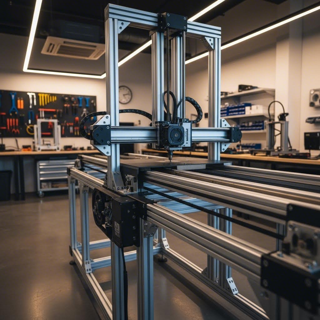
Here's something fascinating about linear motion aluminum extrusion: the same fundamental technology powering a hobbyist's weekend 3D printer project also drives million-dollar industrial automation lines. The difference isn't in the underlying engineering principles but in scale, precision requirements, and component selection. Whether you're building rails for a camera slider in your garage or specifying motor rails for a factory pick-and-place system, you're working with the same core concepts.
This versatility explains why aluminum extrusion v slot systems have captured such diverse markets. Let's explore how these applications span from desktop creativity to industrial production floors.
Walk into any makerspace or home workshop, and you'll spot vrails and aluminum extrusion systems everywhere. The maker community embraced this technology early, recognizing that affordable, modular components could democratize precision motion that previously required industrial budgets.
Consider the applications transforming creative possibilities:
What unites these applications? They all benefit from the maker-friendly nature of aluminum extrusion systems. Components bolt together without welding. Adjustments happen with simple hand tools. Mistakes during initial assembly can be corrected without scrapping expensive parts. This forgiving nature encourages experimentation and iteration that rigid, welded frames simply don't allow.
Step onto a modern factory floor and you'll find the same technology operating at dramatically different scales. Industrial applications push aluminum extrusion linear motion systems to their performance limits while demanding reliability measured in years of continuous operation.
Industrial implementations typically specify heavier profile series, precision ball bearing guides rather than V-wheels, and drive systems matched to demanding duty cycles. The fundamental technology remains identical to desktop applications, but component selection reflects different priorities: maximum uptime, predictable maintenance schedules, and performance specifications backed by engineering calculations rather than trial and error.
The scaling principle works beautifully in both directions. Prototypes developed on desktop equipment using affordable components can graduate to production versions with upgraded specifications. Conversely, proven industrial designs can inspire simplified versions accessible to individual makers. This bidirectional knowledge transfer keeps both communities advancing rapidly.
Understanding where these systems succeed prepares you for the practical challenge ahead: actually building one. Proper assembly and alignment separate functioning systems from frustrating failures, regardless of whether you're working on a desktop project or an industrial installation.
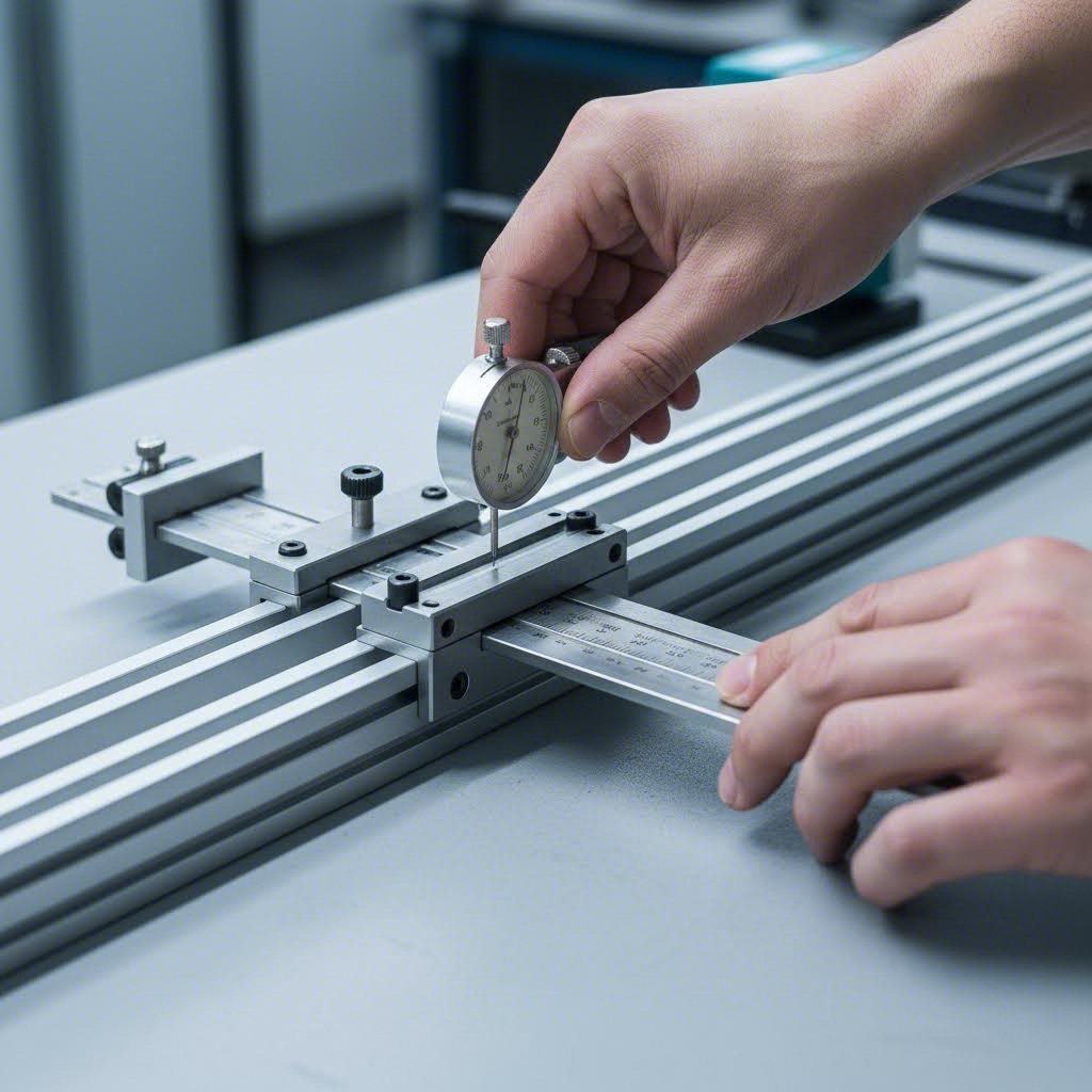
You've selected your aluminium rail extrusions, chosen the right bearings, and specified an appropriate drive system. Now comes the moment of truth: actually putting it all together. Here's where many projects go sideways. Even perfect components assembled poorly deliver frustrating results, with binding, inconsistent motion, or precision that falls far short of expectations.
The difference between a system that performs beautifully and one that constantly disappoints often comes down to assembly technique rather than component quality. Let's walk through the essential steps that transform a pile of parts into a precision motion system.
Think of rail slot alignment like laying railroad tracks. If the rails aren't parallel and level, the train derails. Your linear motion system follows the same principle, just at tighter tolerances. Before tightening a single bolt permanently, you need a systematic approach to ensure everything sits exactly where it should.
The mounting surface matters enormously. An extruded rail bolted to a warped or twisted base will conform to those imperfections. Before mounting aluminum extrusion rails, verify your base surface is flat and true. Use a straightedge and feeler gauges to check for gaps. Any inconsistency here propagates through your entire system.
Proper rail alignment means nothing if your bearings aren't adjusted correctly. Too loose, and you get wobble and inconsistent positioning. Too tight, and you create excessive friction that strains motors and accelerates wear. Finding the sweet spot requires patience and methodical adjustment.
For V-wheel systems common on extruded rail setups, eccentric spacers provide the adjustment mechanism. These offset nuts allow fine-tuning of wheel preload against the rail surface.
Ball bearing carriages on aluminum extrusion rails typically come pre-loaded from the factory, but verify manufacturer specifications. Some systems allow preload adjustment through set screws or shim selection. Insufficient preload allows positioning errors; excessive preload creates heat and premature wear.
Knowing what to avoid saves hours of troubleshooting. These errors appear repeatedly in failed builds:
Take your time during assembly. Rushing this phase to start using your machine faster invariably leads to disassembling everything later to fix problems that proper initial setup would have prevented. The extra hour spent on careful alignment pays dividends across thousands of hours of reliable operation.
With your system properly assembled and aligned, you might wonder whether standard profiles meet your specific needs or whether custom solutions could better address unusual requirements.
Here's a reality most suppliers won't tell you: standard aluminum extrusion profiles handle roughly 80% of linear motion applications beautifully. They're readily available, cost-effective, and proven across countless installations. But what about that remaining 20%? When your project involves unusual load distributions, tight space constraints, or specialized performance requirements, forcing standard components into non-standard situations creates headaches that custom solutions eliminate entirely.
The decision between off-the-shelf and custom t rail extrusion isn't about prestige or budget size. It's about honest assessment of whether standard options truly meet your needs or whether you're compromising in ways that will haunt you throughout the project's lifespan. Let's explore when custom becomes the smarter path forward.
How do you know when standard profiles won't cut it? Several scenarios consistently push projects beyond what catalog options can deliver. Recognizing these situations early saves significant time and frustration compared to discovering limitations mid-build.
Unusual Load Distributions
Standard aluminium extrusion rail profiles are optimized for common loading scenarios. When your application involves eccentric loads, moment forces, or weight distributions that don't align with typical use cases, standard profiles may deflect unacceptably or require oversizing that wastes space and material. Custom profiles can place material exactly where stress concentrates, creating lighter yet stiffer solutions than standard alternatives.
Space Constraints Demanding Specific Geometries
Sometimes your machine design leaves a 37mm gap where standard 30mm and 40mm profiles both fail to fit optimally. Custom extrusion eliminates these compromises. Rather than redesigning your entire machine around available profile dimensions, custom dies produce exactly the cross-section your application requires.
Integrated Mounting Features
Standard profiles require brackets, adapters, and additional hardware to mount motors, sensors, and accessories. Custom extruded aluminum railing can incorporate mounting provisions directly into the profile geometry. According to industry research, eliminating separate brackets through integrated features can reduce assembly time by up to 40%. This translates to lower labor costs and fewer parts to inventory, source, and potentially fail.
Specialized Surface Requirements
Linear motion applications sometimes demand surface characteristics standard profiles don't offer. You might need hardened wear surfaces in specific areas, integrated heat dissipation features, or profile geometries that accept proprietary bearing systems. Custom extrusion addresses these requirements from the start rather than through expensive secondary operations.
Volume Production Economics
Here's a counterintuitive reality: custom profiles sometimes cost less than standard options at sufficient volumes. When your design requires multiple standard components assembled together, a single custom profile replacing that assembly can reduce total cost while improving performance. The breakeven point varies by complexity, but projects consuming hundreds or thousands of linear meters often find custom solutions economically compelling.
Understanding how custom aluminum extruded rail profiles move from concept to production helps you evaluate potential manufacturing partners and set realistic timeline expectations. The process involves several distinct phases, each critical to final product quality.
Step 1: Design and Engineering Collaboration
The journey begins with translating your requirements into manufacturable geometry. This involves more than simply drawing a cross-section. Experienced die designers consider material flow characteristics, wall thickness uniformity, and thermal management that affect both extrudability and final product performance. Early collaboration between your engineering team and the extrusion manufacturer identifies potential issues before expensive tooling begins.
Step 2: Die Development and Manufacturing
The extrusion die is essentially a precision steel disk containing the opening that shapes your profile. Dies are typically machined from H13 tool steel, chosen for its excellent thermal conductivity, wear resistance, and toughness under the extreme pressures involved. Die manufacturing requires specialized equipment and expertise, as tolerances directly affect dimensional accuracy of every meter of profile produced.
Step 3: Extrusion and Initial Production
With dies completed, aluminum billets are heated and forced through the die opening under immense pressure. Production extrusion presses range from small units for intricate profiles to massive systems exceeding 5000 tons of force for large cross-sections. Temperature control, extrusion speed, and cooling parameters all influence final mechanical properties and surface quality.
Step 4: Post-Extrusion Processing
Raw extrusions require additional processing before becoming finished components. This typically includes:
Step 5: Quality Verification and Production Release
Before volume production, samples undergo dimensional inspection and testing against specifications. This validation ensures the die produces conforming parts consistently. Once approved, production scaling begins with ongoing quality monitoring throughout manufacturing runs.
Not all extrusion manufacturers offer equal capability for custom linear motion profiles. Evaluating potential partners requires understanding what separates adequate suppliers from exceptional ones.
Manufacturing capacity matters significantly. A partner with diverse extrusion press sizes, like Shengxin Aluminium's facility featuring 35 extrusion presses ranging from 600T to 5500T, can match appropriate equipment to your profile requirements. Smaller presses excel at intricate profiles with fine details, while larger presses handle substantial cross-sections efficiently.
End-to-end capability streamlines projects considerably. When your extrusion partner also provides CNC machining for precise cutting, drilling, and bending, plus surface treatments including anodizing and powder coating, you avoid coordinating multiple vendors and the quality issues that arise when components transfer between facilities.
Technical support throughout the process distinguishes partners from mere suppliers. Experienced teams that assist from die development through mass production catch potential problems early and optimize designs for manufacturability. This collaborative approach typically produces better results than simply submitting drawings and waiting for quotes.
Consider also the supplier's experience with linear motion applications specifically. General extrusion expertise doesn't automatically translate to understanding the precision and surface requirements that motion systems demand. Ask about previous projects involving similar applications and request references from comparable customers.
Custom extrusion represents a significant commitment, but for applications where standard profiles truly fall short, the investment pays dividends through optimized performance, simplified assembly, and components precisely matched to your requirements. The key lies in honest assessment of whether your project genuinely needs custom solutions or whether standard options, properly selected and assembled, will serve equally well.
With your profile solution identified, whether standard or custom, the final step involves synthesizing all these considerations into a coherent selection framework that guides your project from concept to successful implementation.
You've absorbed a lot of information about v slot rail systems, bearing types, profile sizing, and drive mechanisms. Now comes the practical question: how do you pull all these considerations together into confident decisions for your specific project? Whether you're specifying an aluminum linear rail system for a desktop build or an industrial automation line, a structured selection framework prevents costly oversights and ensures your components work together seamlessly.
Think of this final step as assembling a puzzle where each piece must fit precisely with the others. Selecting a premium v slotted aluminum insert means nothing if your drive system can't deliver required speeds, or if your supplier lacks the capability to produce components meeting your specifications. Let's build the decision framework that connects requirements to solutions.
Before contacting suppliers or adding items to shopping carts, work through these essential considerations systematically. Skipping steps here leads to mismatched components, performance shortfalls, or budget overruns that proper planning prevents.
Component selection and supplier selection are inseparable decisions. The best-specified system means nothing if your supplier can't deliver components meeting those specifications consistently. Here's what separates adequate suppliers from manufacturing partners who contribute to your project's success.
The right manufacturing partner functions as an extension of your engineering team, contributing expertise that improves your final product rather than simply filling orders.
Matching technical requirements with manufacturing capability determines whether your linear motion project succeeds or struggles. A supplier offering comprehensive support from die development through mass production, backed by decades of experience and diverse processing capabilities, provides value far beyond component pricing alone.
Your linear motion system represents an investment in precision, reliability, and performance. Whether you're building your first desktop CNC or specifying equipment for a production facility, the framework outlined throughout this guide equips you to make informed decisions at every step. Start with clear requirements, select components systematically, verify supplier capability thoroughly, and assemble with care. The result will be motion systems that perform exactly as designed, project after project.
T-slot profiles feature perpendicular T-shaped channels designed primarily for modular framing connections, requiring separate linear bearing systems for motion applications. V-slot profiles have angled 45-degree grooves that accept V-wheels directly, providing integrated linear motion capability within the profile itself. V-slot excels for motion-focused projects like 3D printers, while T-slot offers greater versatility for reconfigurable industrial frames and accessory mounting.
V-Slot linear rails serve as both structural framing and motion guidance systems in applications requiring smooth, controlled movement. Common uses include 3D printers, CNC routers, laser cutters, camera sliders, and pick-and-place automation systems. The integrated V-groove design allows V-wheels to ride directly in the channel, reducing component count and simplifying assembly compared to systems requiring separate linear bearings.
Select profile size based on load capacity, span length, and required rigidity. 10 series profiles (10mm cross-sections) suit lightweight desktop applications with short spans under 300mm. 20 series handles medium-duty projects like standard 3D printers with spans up to 600mm. 30 and 40 series profiles support heavy loads and extended spans exceeding 1000mm for industrial CNC machines. Always apply a 1.5x to 2x safety factor to your calculated load requirements.
Three primary bearing types serve different needs: V-wheels offer affordable, maintenance-free operation ideal for hobby projects with moderate precision requirements. Linear ball bearings provide higher accuracy and load capacity for professional CNC machines and precision equipment. Roller bearing systems handle the heaviest industrial loads where maximum rigidity and durability are essential. Match bearing type to your precision, load, and budget requirements.
Custom profiles make sense when standard options create compromises affecting performance. Consider custom extrusion for unusual load distributions requiring optimized material placement, space constraints demanding specific geometries, integrated mounting features that eliminate bracket assemblies, or volume production where consolidated designs reduce total costs. Partners like Shengxin Aluminium offer comprehensive custom services from die development through mass production with 35 extrusion presses and complete CNC machining capabilities.



 online service
 0086 136 3563 2360
 sales@sxalu.com
 +86 136 3563 2360
 English
 français
 Deutsch
 русский
 español
 português
 العربية
 ไทย
ไทย Việt
Việt Українська