Part F of Schedule 1 to the Building Regulations 2010 is the legal requirement in England that every building must have adequate means of ventilation. It is not a design manual, a specification sheet, or a how-to guide. It is a functional requirement written into law, and it says, in essence, one thing: buildings need enough ventilation to protect the health of the people inside them.
Sounds simple? In principle, it is. In practice, the confusion starts almost immediately — because most people use "Part F" and "Approved Document F" interchangeably. They are not the same thing, and understanding the difference is the first step toward getting compliance right.
Requirement F1 (Means of ventilation): There shall be adequate means of ventilation provided for people in the building.
That single sentence is the actual legal obligation. Everything else — the ventilation rates, the system types, the trickle vent sizing tables — lives in Approved Document F, which is the government's statutory guidance on how to satisfy that requirement.
Part F building regulations set a performance-based legal standard. Think of it as the destination: your building must be adequately ventilated. Approved Document F, on the other hand, is one accepted route to that destination. It carries a presumption of compliance, meaning if you follow its guidance, building control will generally accept that you've met the legal requirement. But it is advisory, not mandatory. You could, in theory, demonstrate compliance through an alternative approach — provided you can prove it achieves the same or better outcomes.
This distinction matters more than it might seem. When a building control officer inspects your project, they are checking whether you've met the functional requirement of Part F. They'll typically use Approved Document F as their benchmark, but the legal test is adequacy of ventilation, not rigid adherence to every table and diagram in the guidance.
The current technical guidance is published in two volumes. Volume 1 applies to dwellings and provides prescriptive ventilation rates, system options, and component specifications for houses and flats. Volume 2 covers buildings other than dwellings — offices, schools, retail units, and other non-domestic structures — with a more performance-based approach that accounts for air conditioning systems, airborne illness risk, and commercial occupancy patterns.
You might assume these ventilation requirements only concern architects and mechanical engineers. In reality, the audience is far broader:
Whether you're replacing a few windows in a Victorian terrace or specifying a whole-house mechanical ventilation system for a new-build development, the part F building regulations ventilation requirements apply to your project. The challenge is that the official Approved Documents run to over 100 pages of technical detail, while most online summaries strip out so much context that they become unreliable.
This guide bridges that gap. Each section ahead unpacks a specific aspect of compliance — from the four recognized ventilation systems and their minimum airflow rates, to trickle vent sizing, refurbishment obligations, and exactly what building control inspectors check before they'll sign off your project. The regulatory framework itself has a story worth telling, and that story begins with how these requirements evolved into the two-volume structure we work with today.
Ventilation requirements in English building regulations didn't arrive fully formed. They developed over decades in response to changing construction methods, tightening energy standards, and growing evidence that indoor air quality directly affects occupant health. Understanding this history isn't just academic — it explains why the current rules look the way they do and helps professionals anticipate where they're heading next.
The regulatory journey from broad principles to today's detailed two-volume guidance a clear trajectory, with each revision responding to specific construction industry challenges:
Each step the same pattern: as energy efficiency requirements made building envelopes tighter, the need for controlled, specified ventilation became more urgent. The regulations didn't change in isolation — they evolved because construction practice demanded it.
Before 2022, a single Approved Document covered everything from a two-bedroom flat to a commercial warehouse. The split into two volumes wasn't cosmetic — it reflected fundamentally different ventilation challenges in domestic and non-domestic settings.
Volume 1 addresses dwellings with prescriptive ventilation rates and four recognized system types. It tells you exactly how many litres per second of extract air a kitchen needs, what equivalent area your trickle vents must provide, and how to calculate whole-dwelling ventilation based on bedroom count. This prescriptive approach suits residential construction, where building geometries and occupancy patterns are relatively predictable.
Volume 2 covers buildings other than dwellings — offices, schools, hospitals, retail spaces — using a more performance-based approach. These structures vary enormously in layout, occupancy density, and internal heat gain, so rigid prescriptive rates would be impractical. Instead, Volume 2 provides frameworks for demonstrating that a ventilation strategy achieves adequate air quality for the specific building use.
The restructuring also deliberately aligned Part F with two other critical regulatory updates. Part L's tighter fabric standards mean modern homes lose less heat through walls and roofs, but they also trap more moisture, CO2, and pollutants indoors unless ventilation compensates. Part O, introduced simultaneously, addresses overheating risk — and the openable windows that provide purge ventilation under Part F often double as the passive cooling strategy under Part O. These three regulations now form an interconnected framework where a design decision affecting one inevitably touches the others.
This interconnected reality shapes every practical ventilation decision — and nowhere is that more visible than in the four distinct ventilation systems that Volume 1 recognizes for dwellings.
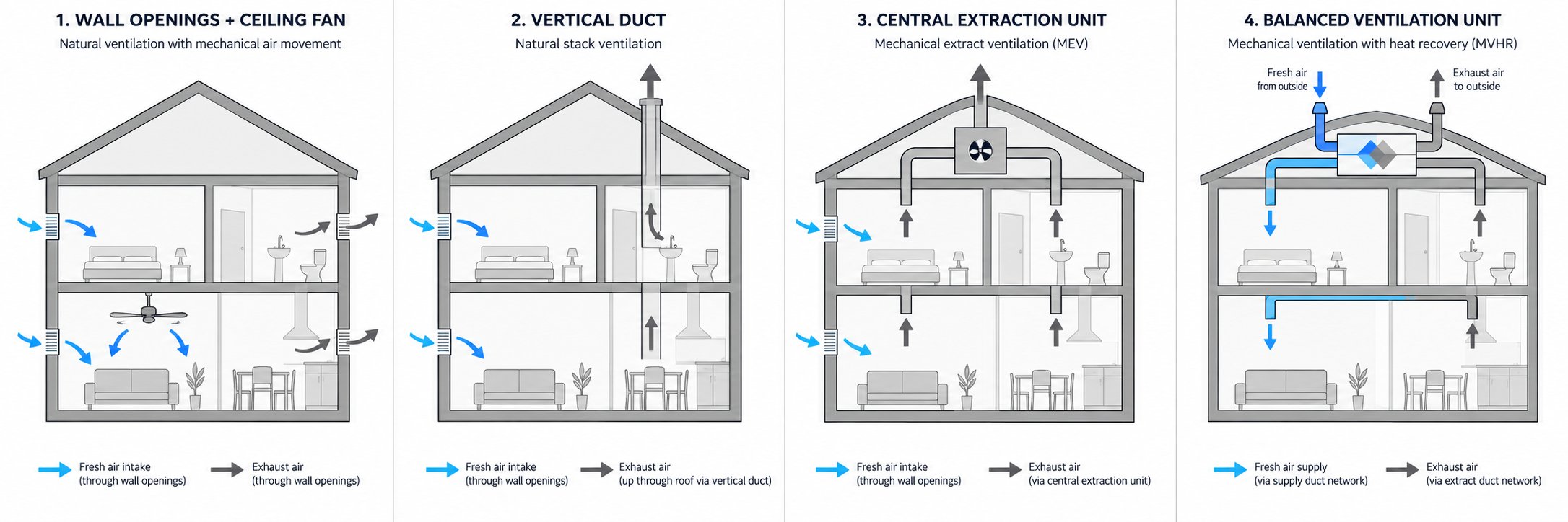
Volume 1 of Approved Document F doesn't leave you guessing about how to ventilate a dwelling. It recognizes exactly four ventilation systems, each with its own combination of air supply and extract methods. Choosing between them shapes everything from ductwork layout and window specification to long-term energy performance — and yet, most guidance online either glosses over the differences or only discusses one or two options in detail.
Here's how all four systems actually work, where each one excels, and where each one falls short.
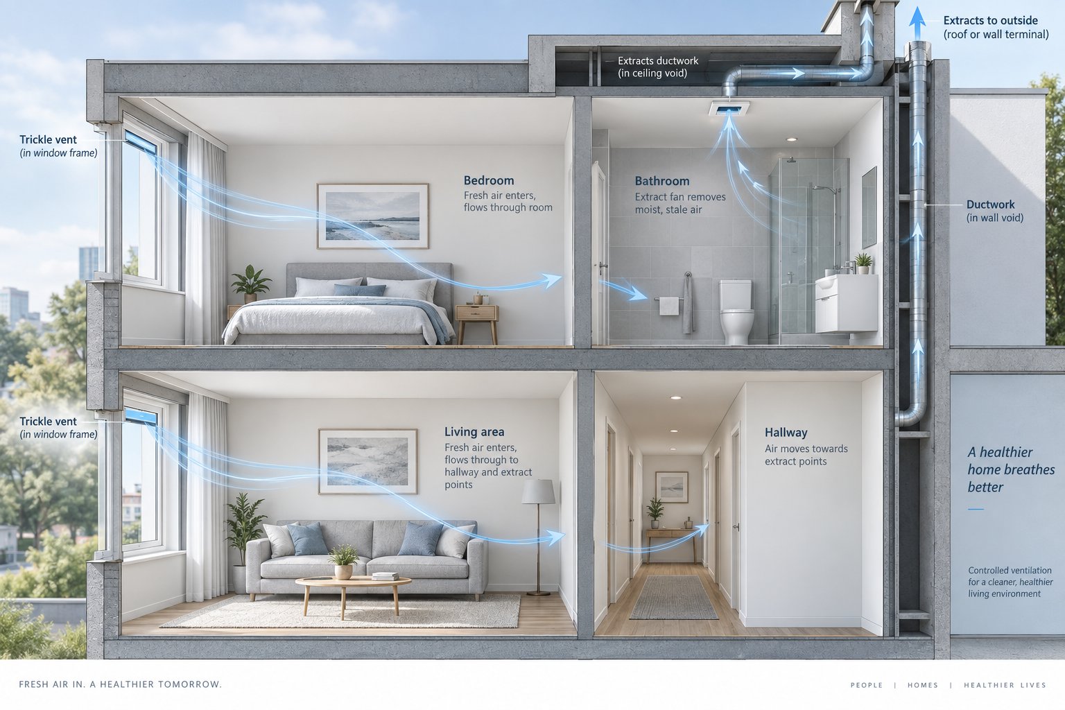
This is the most common approach in standard new-build and refurbishment projects, and the simplest to understand. Trickle vents fitted into window frames or walls provide continuous background airflow throughout the dwelling. In wet rooms — kitchens, bathrooms, and utility rooms — intermittent extract fans activate when moisture or pollutant levels rise, typically triggered by a light switch, humidity sensor, or manual control.
Imagine cooking dinner with the extractor hood running and a trickle vent in the living room quietly letting fresh air seep in. That's System 1 in practice. It requires no central ductwork, no plant room space, and minimal ongoing maintenance. The trade-off? There's no heat recovery, so in winter, the incoming air is as cold as the outside temperature.
Passive stack ventilation relies on natural physics rather than electricity. Vertical ducts running from wet rooms up through the roof use the buoyancy of warm, moist air — which naturally rises — to draw stale air upward and out. Fresh replacement air enters through background ventilators in habitable rooms, just as in System 1.
This system works best in buildings with suitable vertical geometry, where ducts can run straight and unobstructed from ground-floor wet rooms to roof-level terminals. It's quiet, has zero running costs, and involves no mechanical components that could fail. However, its effectiveness depends heavily on temperature differentials between indoors and outdoors, meaning performance can drop significantly in warm weather when the stack effect weakens. Wind conditions and duct length also influence airflow rates, making it less predictable than mechanical alternatives.
Often referred to as MEV (or dMEV for decentralized versions), System 3 uses fans to continuously extract air from wet rooms at low, steady flow rates. Fresh air enters passively through background ventilators — trickle vents or wall vents — in habitable rooms. Centralized MEV systems use a single fan unit connected to extract points in multiple rooms via ductwork. Decentralized versions place individual low-wattage fans directly in each wet room.
Continuous extract is particularly relevant for airtight dwellings. Under current guidance, homes with a design air permeability of 5 m³/h·m² at 50 Pa or less must use a continuous mechanical system — either System 3 or System 4 — because natural air infiltration alone can no longer be relied upon to deliver adequate ventilation. The constant low-level extraction also helps control humidity before condensation becomes a problem.
MVHR represents the most sophisticated approach to domestic ventilation under the part F building regulations. A central unit simultaneously extracts stale air from wet rooms and supplies filtered fresh air to habitable rooms through separate duct networks. Inside the unit, a heat exchanger transfers warmth from the outgoing airstream to the incoming one — modern units achieve heat recovery efficiency ratings of up to 95%.
For highly insulated, airtight new builds pursuing ambitious energy targets, System 4 often becomes the only logical choice. It satisfies ventilation requirements without the energy penalty of introducing cold, untempered outside air. The flip side? MVHR systems require careful ductwork design, dedicated space for the central unit (typically in a utility room or loft), and regular filter maintenance. Installation complexity and upfront costs are significantly higher than the other three systems.
The right system depends on building type, airtightness level, budget, and long-term performance goals. The following comparison lays out the key differences across all four systems recognized under Approved Document F Volume 1:
| Criteria | System 1 — Background Ventilators + Intermittent Extract | System 2 — Passive Stack Ventilation | System 3 — Continuous Mechanical Extract (MEV) | System 4 — MVHR |
|---|---|---|---|---|
| How it works | Trickle vents provide background air; extract fans in wet rooms run intermittently | Warm air rises through vertical ducts from wet rooms to roof; background vents supply fresh air | Centralized or decentralized fans continuously extract from wet rooms; passive air inlets supply fresh air | Balanced supply and extract via central unit with heat exchanger; filtered air delivered to habitable rooms |
| Advantages | Simple, low cost, minimal maintenance, no ductwork needed | No running costs, silent operation, no mechanical components to maintain | Reliable continuous extraction, effective humidity control, suitable for airtight homes | Heat recovery up to 95%, filtered air supply, best IAQ performance, suits high-performance builds |
| Disadvantages | No heat recovery, relies on occupant use of fans, less effective in very airtight homes | Performance varies with weather, needs vertical duct runs, limited to certain building geometries | No heat recovery, background vents still admit cold air, fan noise if poorly specified | High installation cost, requires ductwork routing and plant space, ongoing filter maintenance essential |
| Best suited building types | Standard new builds and refurbishments with moderate airtightness | Low-rise dwellings with clear vertical duct paths and moderate airtightness | Airtight new builds and retrofits where heat recovery is not cost-justified | Highly airtight new builds, Passivhaus projects, and energy-performance-driven developments |
| Typical installation cost | Low | Low to medium | Medium | High |
| Running cost | Low (fans run intermittently) | None (fully passive) | Low (continuous low-wattage fans) | Low to medium (continuous fans offset by heating energy savings) |
| Suitable for air permeability ≤5 m³/h·m² at 50 Pa | No — continuous mechanical ventilation required | No — continuous mechanical ventilation required | Yes | Yes |
When comparing System 1 vs System 4 ventilation under the building regulations, the fundamental question is airtightness. A traditionally built home with moderate air permeability can rely on trickle vents and intermittent extract fans without issue. A dwelling built to near-Passivhaus standards simply cannot — its envelope is too tight for passive airflow strategies to deliver adequate ventilation. MVHR becomes not just preferable but necessary in these cases.
For projects sitting somewhere in the middle, System 3 offers a practical compromise: continuous mechanical extraction without the ductwork complexity and cost of a full MVHR installation. Passive stack ventilation remains a viable option for specific building geometries but is rarely specified in volume housebuilding due to its dependence on environmental conditions and vertical duct routing constraints.
Selecting the right system is only half the equation. Each one must also deliver specific minimum airflow rates — measured in litres per second — for every room type in the dwelling. Those numbers are where compliance gets precise, and where many projects encounter their first problems.
Knowing which ventilation system to use is only useful if you also know the airflow numbers it has to hit. Building control won't accept a fan just because it's installed in the right place — it has to deliver a specific minimum extract rate, measured in litres per second (l/s), verified against the manufacturer's performance data and, for mechanical systems, confirmed through commissioning tests. These are the numbers that separate a compliant installation from a rejection notice.
Approved Document F Volume 1 publishes these rates across two key tables: Table 1.1 for intermittent extract systems and Table 1.2 for continuous mechanical extract systems. A third table — Table 1.3 — sets whole-dwelling ventilation rates based on bedroom count. Together, these three tables define the quantitative backbone of domestic ventilation compliance under the part F building regulations.
Every wet room in a dwelling needs extract ventilation, regardless of whether it has an openable window. A bathroom with a large sash window still requires a fan delivering at least 15 l/s. The only partial exception is sanitary accommodation — a WC or cloakroom without a bath or shower — where purge ventilation via an openable window can substitute for a mechanical fan at the 6 l/s level.
One detail catches many installers off guard: the kitchen extract fan flow rate under building regulations depends on whether the cooker hood ducts to the outside. A recirculating cooker hood — the type that filters air and pushes it back into the room — does not count as Part F ventilation at all. If the hood doesn't extract to the outside, you need a separate fan capable of delivering 60 l/s. That's double the rate required when a properly ducted hood is present.
The table below consolidates the minimum extract ventilation rates in litres per second for each room type, drawn directly from Approved Document F Volume 1 Tables 1.1 and 1.2:
| Room Type | Intermittent Extract Rate (System 1 — Table 1.1) | Continuous Extract High Rate (Systems 3 & 4 — Table 1.2) |
|---|---|---|
| Kitchen (cooker hood extracting to outside) | 30 l/s | 13 l/s |
| Kitchen (no hood, or hood that only recirculates) | 60 l/s | 13 l/s |
| Utility room | 30 l/s | 8 l/s |
| Bathroom (with bath or shower) | 15 l/s | 8 l/s |
| Sanitary accommodation (WC / cloakroom) | 6 l/s | 6 l/s |
Notice the gap between intermittent and continuous rates. A bathroom fan running intermittently — switching on when someone showers and off when they leave — needs to deliver 15 l/s during those brief operating periods. A continuous system, running constantly at a low background rate, only needs to deliver 8 l/s at its high-rate boost setting because it never stops extracting. The continuous approach catches moisture before it accumulates, while the intermittent approach has to compensate by moving a larger volume of air during shorter bursts.
A critical practical point: the l/s figure on a fan's packaging is typically its free-air performance — what it delivers with no duct resistance. Install that same fan at the end of a long duct run with two 90-degree bends, and the actual delivered flow rate could drop by 25% or more. Each 90-degree bend adds roughly 1.5 metres of equivalent duct length in terms of resistance. Always verify the fan's performance against the specific installed duct configuration, not its headline rating.
Room-level extract rates are only half the picture. Approved Document F also requires the total ventilation across the entire dwelling to meet a minimum whole-dwelling rate. This calculation uses two inputs, and the higher result governs.
The first input is Table 1.3 of Approved Document F Volume 1, which sets minimum rates by bedroom count:
| Number of Bedrooms | Minimum Whole-Dwelling Ventilation Rate |
|---|---|
| 1 bedroom | 19 l/s |
| 2 bedrooms | 25 l/s |
| 3 bedrooms | 31 l/s |
| 4 bedrooms | 37 l/s |
| 5 bedrooms | 43 l/s |
| Each additional bedroom beyond 5 | Add 6 l/s per bedroom |
| Single habitable room (e.g., studio) | 13 l/s |
The second input is a floor-area-based calculation: 0.3 l/s per square metre of total internal floor area across all storeys. Whichever figure is higher — the bedroom-count rate or the floor-area rate — becomes the minimum whole-dwelling ventilation rate that your system must achieve.
Imagine a spacious three-bedroom bungalow with 120 m² of internal floor area. Table 1.3 gives 31 l/s based on three bedrooms. The floor area calculation gives 0.3 x 120 = 36 l/s. Since 36 is higher, the whole-dwelling rate is 36 l/s — not 31. This dual-test approach prevents large dwellings with few bedrooms from being underventilated, and it's a calculation step that's frequently missed in practice.
For continuous mechanical systems (Systems 3 and 4), this whole-dwelling rate also sets the minimum low-rate — the background flow rate the system maintains when not boosted. The sum of all extract flow rates at their minimum continuous setting must at least equal the whole-dwelling ventilation rate. This is how room-level and dwelling-level requirements connect: individual room rates handle localized pollutants, while the whole-dwelling rate ensures adequate overall air exchange for health and moisture control.
Beyond background and extract ventilation, every habitable room needs a purge ventilation capability — a way to rapidly flush the space with fresh air at a rate of at least four air changes per hour. Purge ventilation handles situations that normal ventilation isn't designed for: painting a room, dealing with a smoke event, or simply clearing the air after heavy cooking.
The most common way to achieve this is through openable windows. The required openable area depends on the opening angle:
For a bedroom with 14 m² of floor area and a casement window that opens beyond 30 degrees, the minimum openable area is 14 / 20 = 0.7 m². That's a meaningful window opening — roughly equivalent to a single 700 mm x 1000 mm casement. Fall short, and you'll need to demonstrate an alternative purge route, potentially through mechanical means.
Purge ventilation also intersects with Part O overheating requirements. The same openable windows that provide purge airflow under Part F often serve as passive cooling openings under Part O. In practice, this dual function means window sizing decisions carry regulatory weight from two directions simultaneously — too small for purge ventilation, and you fail Part F; too large or poorly oriented, and you may trigger overheating concerns under Part O.
For new-build dwellings, these ventilation rates don't exist in isolation. They feed directly into the SAP (Standard Assessment Procedure) energy calculation that every new home requires. SAP models the dwelling's energy performance by accounting for heat losses through ventilation alongside fabric losses through walls, floors, roofs, and glazing. The ventilation system type and its airflow rates are core inputs.
Choosing System 4 MVHR with high heat recovery efficiency, for example, dramatically reduces the ventilation heat loss component in SAP — because the heat exchanger reclaims up to 95% of the energy from outgoing air. System 1, with no heat recovery, shows a much higher ventilation heat loss, which must be compensated elsewhere in the design through better insulation or lower-carbon heating.
Specialized ventilation modelling software can also demonstrate compliance through performance-based approaches, calculating airflow distribution across the dwelling rather than relying solely on the prescriptive tables. This is particularly relevant for unusual dwelling layouts where standard system configurations don't fit neatly, or for projects targeting validated reduced air change rates through enhanced system performance.
The airtightness threshold adds another layer. Under the current Approved Document F guidance, dwellings designed to an air permeability of 5 m³/(h·m²) at 50 Pa or less — which includes virtually all new-build homes targeting current Part L compliance — cannot use System 1's natural ventilation approach. They must adopt continuous mechanical ventilation via System 3 or System 4. This makes the interaction between airtightness testing, SAP modelling, and ventilation specification an inseparable design conversation rather than three separate compliance exercises.
These airflow numbers and calculation methods give you the quantitative foundation for specifying ventilation systems. But there's one component that appears in more building control queries than any other — and it's far simpler than a fan or an MVHR unit. It's the trickle vent, and its compliance requirements revolve around a measurement most people have never heard of: equivalent area.
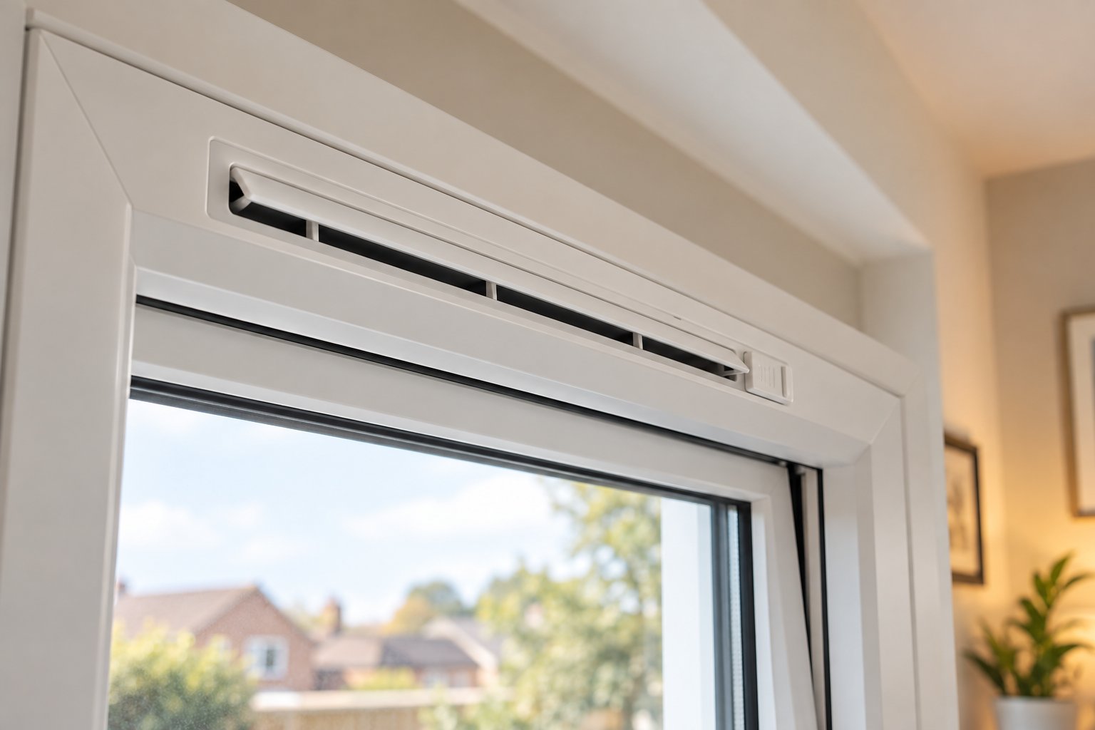
Trickle vents are small, unassuming openings built into or mounted onto window frames — and they generate more building control queries than almost any other ventilation component. The reason is straightforward: they're the primary means of background ventilation in the most widely used domestic ventilation strategy (System 1), yet the metric that governs their sizing — equivalent area — is widely misunderstood. Specifiers quote the wrong number, installers fit undersized vents, and building control rejects the installation. It happens constantly.
Getting trickle vent equivalent area requirements right under Part F is not complicated, but it does require understanding what equivalent area actually measures and why it differs from the physical size of the vent opening.
When you look at a trickle vent, you'll see a physical slot — a rectangular opening in the window frame. You could measure that slot with a ruler, calculate its cross-sectional area in square millimeters, and arrive at what's called the geometric free area. That number tells you the size of the hole. It does not tell you how much air can actually flow through it.
Equivalent area (EA) is the more accurate metric. It measures the aerodynamic performance of the ventilator — how much airflow it delivers after accounting for all the internal resistance created by louvres, baffles, insect screens, and the geometry of the vent's internal passages. Think of it this way: free area is the size of the road, but EA is the actual traffic flow once you account for speed bumps, tight turns, and obstacles along the route.
The relationship between the two is governed by the discharge coefficient (Cd):
Equivalent Area = Geometric Free Area x Discharge Coefficient (Cd)
Since the discharge coefficient for any practical ventilator is always less than 1 — typically somewhere between 0.5 and 0.9 depending on the vent's internal design — the equivalent area will always be smaller than the geometric free area. A vent with a physical opening of 5,000 mm² might only deliver an equivalent area of 3,500 mm² once you factor in the resistance of its internal components.
This distinction matters enormously for compliance. Approved Document F Volume 1 specifies minimum equivalent area values, not free area values. If you size your trickle vents based on geometric free area — a surprisingly common mistake — you'll overestimate their airflow capacity and potentially fail building control inspection. The vent manufacturer's technical data sheet should always state the tested equivalent area, measured in accordance with BS EN 13141-1, which defines the standard test methodology for ventilation components.
The minimum equivalent area mm2 for trickle vents under the building regulations depends on the room type — specifically, whether it's classified as a habitable room or a wet room. The 2022 update to Approved Document F closed a significant loophole around replacement windows and established clearer minimum thresholds that apply to both new-build and replacement window installations.
The following table summarizes the minimum EA requirements under System 1 (background ventilators with intermittent extract fans), as specified in Approved Document F Volume 1:
| Room Type | Minimum Equivalent Area (EA) | Typical Vent Provision | Notes |
|---|---|---|---|
| Living room | 8,000 mm² | 2-3 slot vents (e.g., 2 x 4,000 mm²) | Can be distributed across multiple windows in the same room |
| Main bedroom | 8,000 mm² | 2-3 slot vents | Total EA summed across all windows in the room must meet the threshold |
| Other bedrooms | 8,000 mm² | 2 slot vents or 1 large vent | Same requirement regardless of room size |
| Study / home office | 8,000 mm² | 2 slot vents | Treated as a habitable room |
| Dining room | 8,000 mm² | 2 slot vents | Treated as a habitable room |
| Kitchen | 4,000 mm² + mechanical extract | 1 slot vent + extract fan | Trickle vent provides make-up air for the extract system |
| Bathroom | 4,000 mm² + mechanical extract | 1 slot vent + extract fan | Both vent and fan required — neither alone is sufficient |
| Utility room | 4,000 mm² + mechanical extract | 1 slot vent + extract fan | Same as kitchen and bathroom requirements |
| Cloakroom / WC | 4,000 mm² + extract or humidistat | 1 slot vent + intermittent extract | Humidistat-controlled extract acceptable |
The logic behind the 4,000 vs 8,000 mm² split is intuitive once you see it. Wet rooms at 4,000 mm² have dedicated mechanical extract fans actively pulling air through the trickle vent, so less vent area is needed. Habitable rooms at 8,000 mm² rely entirely on the trickle vent for background air supply, with no mechanical assistance — so the opening needs to be larger to achieve adequate airflow under natural pressure differences alone.
A practical point that trips up many installers: the 8,000 mm² requirement applies per room, not per window. A bedroom with two windows could achieve compliance with two vents of 4,000 mm² each, or three vents of approximately 2,700 mm² each, or any combination that sums to at least 8,000 mm². A bay window with three separate lites can distribute the total EA across all three openings. What matters is the aggregate equivalent area serving that room.
The trickle vent size for habitable rooms under Approved Document F doesn't change based on room dimensions — a compact box bedroom and a sprawling master suite both need 8,000 mm². The underlying assumption is that background ventilation rates for habitable rooms should be broadly consistent regardless of floor area, since the whole-dwelling ventilation rate (discussed in the previous section) already accounts for overall dwelling size through the bedroom-count and floor-area calculations.
Meeting the minimum equivalent area threshold is the baseline — but it's not the only factor that determines whether a trickle vent performs well in practice. Specifiers and window manufacturers evaluating how to choose compliant trickle vents for windows should consider multiple performance criteria simultaneously, because a vent that technically passes Part F can still create problems if it introduces excessive noise, doesn't integrate cleanly with the window frame, or restricts airflow due to poor internal design.
Here are the key selection criteria for trickle vents that go beyond bare regulatory compliance:
For architects and contractors sourcing compliant components, manufacturer product pages that provide verified equivalent area data, acoustic ratings, and frame compatibility specifications are invaluable. Shengxin Aluminium's window trickle vent range, for instance, offers noise-conscious passive ventilation designed for direct integration with uPVC and aluminium window systems — the kind of product data that streamlines specification and reduces the risk of compliance gaps during building control inspection.
One final point worth emphasizing: since 15 June 2022, replacement windows in England must include trickle ventilation unless an alternative ventilation strategy is documented and justified. The customer cannot waive this requirement, and the installer carries the compliance duty. This regulatory change transformed trickle vents from an optional feature to an unavoidable component of virtually every domestic window installation — and it's a change that applies equally to new builds, refurbishments, extensions, and conversions.
Most ventilation guidance focuses on new-build dwellings — clean-sheet designs where you can plan ductwork routes, specify system types from scratch, and integrate trickle vents into brand-new window frames. But the majority of building work in England isn't new construction. It's extensions, loft conversions, garage conversions, window replacements, and change-of-use projects in existing buildings. And these projects trigger part F building regulations obligations that many homeowners and even some contractors only discover when building control flags a problem during inspection.
The rules for existing buildings aren't simply a watered-down version of new-build requirements. They follow a distinct logic, apply through different trigger mechanisms, and create compliance challenges that don't exist on a greenfield site.
The governing principle for ventilation in existing buildings comes down to a single, deceptively simple rule: the ventilation provision must not be made worse than the existing situation as a result of the building work. This is codified under Regulation 4(3) of the Building Regulations 2010, and it applies to every type of building work — not just projects that are obviously ventilation-related.
Sounds straightforward? In practice, it creates a compliance test that trips up thousands of projects every year. The most common scenario involves replacement windows.
Imagine you're replacing the original timber casement windows in a 1930s semi-detached house with new uPVC double-glazed units. The old windows were draughty — they leaked air around warped frames, cracked putty, and poorly fitting sashes. That uncontrolled air leakage was, in regulatory terms, providing background ventilation. Your new windows are far more airtight. Without trickle vents, you've just made the building's ventilation significantly worse — even though the windows themselves are better in every other respect.
This is exactly why current guidance recommends that replacement windows are fitted with background trickle ventilators. If the original windows had trickle vents, the replacements must include them. If the original windows didn't have trickle vents but the building's ventilation strategy relies on background ventilation through the window openings, new trickle vents should be installed to compensate for the improved airtightness of the replacement units.
Several common workarounds that homeowners and installers attempt simply don't satisfy the regulations:
There is, however, one practical exception worth noting. When a room already has a wall-mounted ventilator that meets the minimum equivalent area thresholds specified in Approved Document F Volume 1, no additional background ventilation needs to be added after replacing the windows. The existing wall vent is already providing the required background airflow, so the new windows don't make the ventilation worse. This exception doesn't apply to air vents serving open-flued appliances — those vents meet Part J combustion air requirements and cannot be counted toward Part F background ventilation.
Members of competent person schemes who self-certify replacement window installations carry direct responsibility here. The scheme requires them to confirm that the work complies with all relevant Building Regulations requirements, including Regulation 4(3). Certifying non-compliant work — windows without adequate trickle ventilation where it's needed — can result in enforcement action against the installer by the scheme operator.
Replacement windows are the most frequent trigger, but Part F obligations extend to a much broader range of renovation projects. Each scenario has its own compliance logic, and the requirements become more demanding as the scope of work increases.
Kitchen extensions are one of the most common domestic building projects — and they consistently generate ventilation compliance questions. When you extend a kitchen or create a new open-plan kitchen-diner, the ventilation requirements for a kitchen extension under building regulations include both extract ventilation and background ventilation for the new space. You'll need an extract fan or cooker hood ducted to the outside meeting the minimum flow rates (30 l/s with a ducted hood, or 60 l/s without), plus trickle vents in any new windows providing the required equivalent area. If the extension connects to existing rooms, building control will also check that the ventilation strategy for those rooms hasn't been compromised — for instance, by removing an external wall that previously contained a window with trickle vents.
Loft conversions create an entirely new habitable room within the building envelope, and the part F ventilation requirements for loft conversions reflect that. The converted loft space needs background ventilation — typically achieved through trickle vents in new dormer windows or rooflights — and purge ventilation capability through openable windows sized to deliver at least four air changes per hour. If the loft includes an en-suite bathroom or shower room, that wet room requires its own mechanical extract fan meeting the minimum l/s rates, plus a background ventilator. Rooflights with integrated trickle vents typically satisfy the background ventilation requirement for loft bedrooms and home offices, but you'll want to verify that the specific rooflight model provides adequate equivalent area.
Garage conversions follow similar principles. Converting a garage into a habitable room — a bedroom, home office, or playroom — means the new space must meet full Part F requirements for a habitable room. Background ventilation via trickle vents (minimum 8,000 mm² equivalent area for habitable rooms under System 1), purge ventilation through openable windows, and mechanical extract if the conversion includes a wet room. The challenge with garage conversions is that the original space typically had no controlled ventilation at all — perhaps a large up-and-over door and some air bricks. The conversion strips these out and replaces them with insulated walls and sealed windows, making deliberate, specified ventilation essential rather than optional.
Commercial-to-residential change of use represents the most demanding scenario. When a building changes use class from commercial to residential — an office becoming flats, a shop converting to a dwelling, a warehouse becoming live-work units — the ventilation requirements shift entirely. The new residential units must comply with Approved Document F Volume 1 in full, as if they were new dwellings. This means implementing one of the four recognized ventilation systems, meeting all minimum extract rates for wet rooms, achieving whole-dwelling ventilation rates based on bedroom count, and providing background and purge ventilation to every habitable room. For permitted development conversions under Class MA or Class O, building control approval is still required, and the ventilation strategy is one of the key elements inspectors assess.
Here are the key trigger points at which Part F obligations apply in renovation scenarios:
That last trigger point deserves special attention. The 2022 amendments to Part F introduced a new requirement specifically targeting energy efficiency retrofits: when work is done to improve a building's energy performance, the ventilation must not be degraded. A mandated checklist was introduced to help renovators understand the impact of both historic and planned work on a building's ventilation provision. This directly addresses the tension between Part L airtightness goals and Part F ventilation needs — as you seal up a building to reduce heat loss, you simultaneously reduce the uncontrolled air infiltration that was previously (if inadequately) ventilating the space.
This intersection of airtightness and ventilation is the single most important design consideration in refurbishment projects. A Victorian terrace with original single-glazed windows and unsealed floorboards might have an air permeability above 15 m³/(h·m²) at 50 Pa — far leakier than modern standards, but providing a substantial volume of uncontrolled background air exchange. Replace the windows, insulate the walls, seal the floors, and that permeability could drop to 5 or 6 m³/(h·m²). The house is warmer and cheaper to heat, but without a compensating ventilation strategy, condensation risk increases dramatically, indoor pollutant concentrations rise, and mould growth becomes almost inevitable.
This is precisely why Part F and Part L cannot be treated as separate compliance exercises in renovation work. Every improvement to the building envelope demands a corresponding assessment of ventilation adequacy — and for deep retrofits that achieve very low air permeability levels, a shift from passive to continuous mechanical ventilation may be the only way to satisfy both regulations simultaneously.
These refurbishment scenarios reveal how ventilation compliance in existing buildings is shaped not just by Part F in isolation, but by its interactions with energy, fire safety, moisture control, and overheating regulations. Those cross-regulatory connections deserve a closer look.
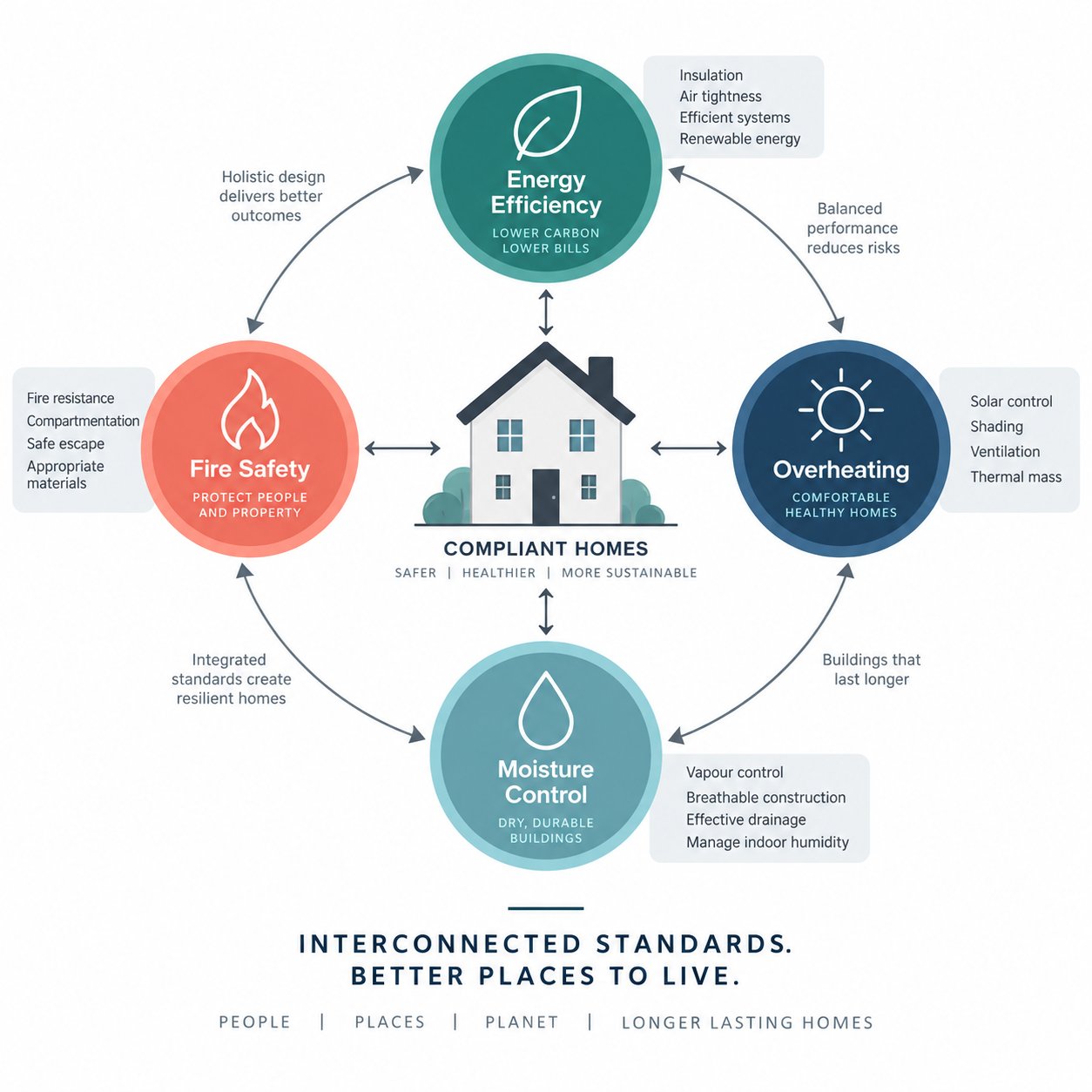
Ventilation doesn't exist in a regulatory vacuum. Every duct route you plan, every trickle vent you specify, and every openable window you size ripples across at least three or four other parts of the Building Regulations. Yet most guidance treats Part F as a standalone exercise — specify your fans, fit your vents, move on. In reality, the decisions you make to satisfy ventilation requirements can create conflicts with energy efficiency targets, fire compartmentation rules, overheating limits, and moisture control principles. Ignoring those connections is how projects end up redesigning ductwork at the eleventh hour or failing inspections on technicalities that weren't even on the ventilation designer's radar.
Here's how Part F connects to the regulations most likely to collide with your ventilation strategy — and how experienced designers resolve those collisions before they reach the building control officer's desk.
This is the tension at the heart of modern building design. Part L demands increasingly airtight building envelopes to conserve fuel and power. Part F demands that those same sealed-up buildings receive enough fresh air to protect occupant health. Tighten the envelope without adding controlled ventilation, and you trap moisture, CO2, and volatile organic compounds inside. Add ventilation without recovering heat, and you blow a hole in your energy performance calculations.
The numbers tell the story. A dwelling built to current Part L standards typically achieves an air permeability of 5 m³/(h·m²) at 50 Pa or below — tight enough that natural background infiltration no longer delivers adequate air exchange. At this level of airtightness, Systems 1 and 2 (trickle vents with intermittent extract or passive stack ventilation) are no longer permitted as the primary ventilation strategy. The dwelling must use continuous mechanical ventilation: either System 3 (MEV) or System 4 (MVHR).
System 4 MVHR often emerges as the resolution to this tension. By recovering up to 95% of the heat from outgoing stale air, it lets you ventilate adequately without the energy penalty of introducing cold, untempered outside air. In SAP calculations, a well-specified MVHR system dramatically reduces the ventilation heat loss component — the single largest variable that separates a borderline Part L pass from a comfortable margin. For high-performance builds pursuing Future Homes Standard targets, MVHR isn't just a ventilation choice; it's an energy strategy.
The practical conflict surfaces in less obvious places too. Every trickle vent represents a small thermal bridge through the window assembly, adding approximately 0.02–0.04 W/m²K to the window's U-value. On a standard double-glazed window, that's within tolerance. On a triple-glazed Passivhaus-certified unit where every fraction of a watt matters, the cumulative thermal impact of six or eight trickle vents across a dwelling becomes a design consideration that needs explicit attention in the Part L calculations.
Since June 2022, Part O has required designers to demonstrate that new residential buildings won't overheat — and the primary mitigation tool it relies on is the same one Part F uses for purge ventilation: openable windows. This overlap means a single window opening can carry regulatory weight from two directions simultaneously.
Under Part F, purge ventilation requires openable window areas of at least 1/20th of the room's floor area (for windows opening beyond 30 degrees). Under Part O, those same openable areas form the basis of the simplified overheating assessment or feed into dynamic thermal modelling under CIBSE TM59. Design a window that's too small, and you fail Part F's purge requirement. Design it too large or on the wrong facade, and you may introduce excessive solar gain that triggers Part O overheating concerns — particularly on south- and west-facing elevations.
The conflicts go deeper than window sizing. Part O's TM59 assessments often assume internal doors can be opened to facilitate cross-ventilation and purge heat from the dwelling. But in multi-storey homes, those doors may be fire-rated under Part B and must remain closed to preserve compartmentation. The ventilation strategy that solves overheating on paper falls apart in practice when fire safety constraints prevent occupants from opening the doors the model relies on.
There's also a commissioning disconnect that catches designers off guard. Part F commissioning records typically express ventilation rates in litres per second, while TM59 overheating reports use air changes per hour. As building control practitioners have noted, ventilation systems commissioned to meet Part F flow rates don't automatically satisfy the airflow assumptions in the TM59 model — the units must be reconciled, and the commissioning documentation must demonstrate compliance with both sets of requirements in their respective formats.
Part B (Fire Safety) intersects with ventilation design wherever ductwork passes through fire-separating elements — compartment walls, compartment floors, and protected corridors. Every penetration through a fire compartment boundary requires fire stopping that maintains the fire resistance of that element. For ventilation ductwork, this typically means installing intumescent fire dampers at compartment boundaries, or using fire-rated rigid steel ductwork where plastic or flexible ducting would compromise fire integrity.
This requirement becomes particularly significant in MVHR installations for multi-storey dwellings. A centralized MVHR unit in the loft of a three-storey house sends supply and extract ducts down through two or more floor zones — each penetration a potential fire path. Rigid steel ducting and robust fire-stopping measures are triggered in these scenarios, adding both cost and design complexity that the ventilation designer must anticipate from the outset rather than resolve as an afterthought.
Part C (Site Preparation and Resistance to Contaminants and Moisture) connects to Part F through condensation prevention. Adequate ventilation is one of the primary defenses against interstitial and surface condensation — the moisture that forms on cold surfaces when warm, humid indoor air isn't extracted quickly enough. A dwelling that satisfies Part F's extract rates for wet rooms and maintains adequate background ventilation across habitable rooms will, in most circumstances, also satisfy Part C's expectation that the building's design limits condensation risk to levels that won't cause damage to the building fabric or endanger occupant health.
The relationship works in reverse too. Poor Part C detailing — cold bridges at window reveals, uninsulated lintels, or inadequately vapour-controlled wall assemblies — can produce localized condensation that no amount of ventilation will fully resolve. Part F compliance reduces the overall moisture load in the indoor air, but it cannot compensate for construction defects that create specific cold spots where condensation concentrates.
The following table maps each related regulation against the specific points where it interacts with Part F, the design conflicts that commonly arise, and the approaches that experienced practitioners use to resolve them:
| Related Regulation | Key Interaction With Part F | Potential Design Conflict | Recommended Resolution |
|---|---|---|---|
| Part L — Conservation of Fuel and Power | Airtight envelopes reduce uncontrolled infiltration, increasing reliance on controlled ventilation; trickle vents add to thermal bridging and U-value calculations | Ventilation heat loss undermines energy performance targets; trickle vents degrade window U-values | Specify System 4 MVHR with high heat recovery efficiency to satisfy both ventilation and energy targets; model trickle vent thermal impact in SAP calculations |
| Part O — Overheating | Openable windows serve dual roles for purge ventilation (Part F) and passive cooling (Part O); TM59 modelling assumes cross-ventilation via internal doors | Window sizing must satisfy purge ventilation minimums without introducing excessive solar gain; fire doors prevent the cross-ventilation that TM59 models assume | Coordinate window sizing with both purge ventilation and TM59 calculations early in design; reconcile l/s and air-changes-per-hour units in commissioning records; consider MVHR boost modes to supplement passive cooling |
| Part B — Fire Safety | Ventilation ductwork penetrates fire compartment boundaries in multi-storey dwellings; duct materials must maintain fire resistance | Flexible or plastic ductwork may not satisfy fire resistance requirements at compartment boundaries; MVHR duct routes through floor zones create fire paths | Install intumescent fire dampers at all compartment penetrations; use fire-rated rigid steel ductwork where required; plan duct routes during structural design stage to minimise compartment crossings |
| Part C — Site Preparation and Resistance to Moisture | Adequate ventilation under Part F reduces indoor humidity, helping prevent surface and interstitial condensation addressed by Part C | Poor thermal detailing (cold bridges, uninsulated reveals) can cause localized condensation that ventilation alone cannot resolve | Combine adequate Part F ventilation with robust Part C thermal detailing; address cold bridges at design stage; use continuous extract in high-humidity rooms to control moisture at source |
What emerges from this cross-regulatory view is a simple but frequently overlooked principle: ventilation design cannot happen at the end of the process. By the time ductwork routes are being planned around fire compartments, window sizes are being debated between overheating modellers and ventilation specifiers, and energy assessors are questioning the thermal impact of trickle vents, it's too late for easy fixes. The most effective compliance strategy treats Part F, Part L, Part O, Part B, and Part C as a single integrated design conversation from day one — not five separate sign-off exercises tackled in sequence.
Knowing how these regulations interconnect is essential for avoiding design conflicts. But even when the design is sound on paper, compliance can still unravel during installation and inspection. The most common failure points aren't exotic engineering problems — they're straightforward mistakes that building control officers encounter on site every week.
A ventilation design can look flawless in the specification documents and still fail on site. Building control officers don't assess your intentions — they assess what's physically installed, whether it performs to the required rates, and whether you can prove it. The most common building control failures related to ventilation under Part F are not obscure engineering shortcomings. They're predictable, preventable mistakes that happen on project after project because the same oversights keep repeating.
Understanding where other projects stumble is the fastest way to make sure yours doesn't.
If one issue dominates Part F compliance rejections in domestic projects, it's this: replacement windows installed without trickle vents — or with vents that don't deliver adequate equivalent area for the room they serve.
The scenario plays out thousands of times a year. A homeowner replaces old timber windows with new uPVC double-glazed units. The installer fits beautiful, draught-free windows — and omits the trickle vents entirely, either because the customer doesn't want them or because nobody flagged the requirement. Building control inspects, identifies that the building's background ventilation has been made worse, and rejects the installation.
As the government's own FAQ guidance makes unambiguously clear, replacement windows without trickle vents will fail building control where background ventilation is needed. A homeowner disclaimer refusing trickle vents doesn't satisfy the regulations. A night-vent latch — a window locked slightly ajar — isn't an acceptable substitute. An indemnity insurance policy doesn't remove the legal obligation. The work must comply at the point of completion, full stop.
Undersizing is almost as common as omission. A habitable room needs 8,000 mm² of equivalent area under System 1. An installer fits a single 4,000 mm² slot vent and assumes it's sufficient. It isn't — the room is 4,000 mm² short, and the shortfall only becomes apparent when the building control officer checks the vent specification against the room schedule. The fix usually means retrofitting additional vents into the window head or adding wall-mounted background ventilators, both of which are more disruptive and expensive after the window is already installed and decorated.
The second major failure category involves extract fans that don't deliver the required airflow — not because they're defective, but because they were either underspecified or never properly commissioned after installation.
Here's a common example. A bathroom extract fan is specified at 15 l/s — the correct intermittent rate for a bathroom under System 1. The fan's datasheet confirms 15 l/s at free-air delivery. But the fan is then connected to a 3-metre duct run with two 90-degree bends and a wall grille on the external face. Each bend adds resistance. The grille adds resistance. The actual delivered flow rate at the extract point drops to 10 or 11 l/s — well below the minimum. The fan technically meets the spec; the installation doesn't.
This is why commissioning matters so much. For mechanical ventilation systems, the ventilation commissioning certificate requirements under the building regulations demand that airflow measurements are taken in situ — at the point of extract, with the full duct run connected — not from a catalogue. The commissioning process involves:
For continuous mechanical systems (Systems 3 and 4), commissioning must verify both the low-rate (background) and high-rate (boost) airflow at every terminal. The sum of all low-rate extract flows must at least equal the whole-dwelling ventilation rate. Each individual terminal must meet the minimum continuous extract rate for its room type. Miss either threshold, and the system fails.
MVHR systems face an additional commissioning requirement: the balance between supply and extract airflows. A well-commissioned MVHR unit should deliver roughly equal volumes of supply air and extract air across the dwelling. A significant imbalance — more air being extracted than supplied, or vice versa — creates pressure differences that either draw unfiltered air through gaps in the building envelope or push conditioned air out through those same gaps, undermining both ventilation effectiveness and energy performance.
Building control expects to see a completed commissioning certificate signed by a competent person before issuing a completion certificate. "Competent person" here means someone with the knowledge and equipment to take accurate airflow measurements — typically the mechanical installer or a specialist commissioning engineer. A certificate that simply states "system installed and working" without recorded flow rates at each terminal will not satisfy inspection requirements.
Even when trickle vents are correctly sized and fans are properly commissioned, projects still stall at sign-off because the documentation doesn't exist or doesn't contain the information building control needs. The ventilation design rationale, the commissioning data, and the component specifications all need to be available for inspection — and in practice, they're often scattered across different contractors' files, incomplete, or never produced in the first place.
Building control officers typically expect to review:
When any of these documents are missing, the sign-off process stalls. The building control officer can't verify compliance from a visual inspection alone. They need the numbers — and the numbers need to be written down, signed, and available on request. Delays caused by chasing missing paperwork are entirely avoidable, yet they remain one of the most frequent causes of extended project timelines.
So what actually happens if ventilation fails a building regulations inspection? The consequences escalate depending on how the non-compliance is handled — and they can become surprisingly severe.
The starting point is usually informal. A building control officer identifies the non-compliance — undersized trickle vents, an uncommissioned fan, missing documentation — and advises the builder or homeowner on what needs to be corrected. Most issues are resolved at this stage through remedial work: fitting additional vents, recommissioning a fan, producing the missing certificate.
If informal resolution fails, the enforcement powers available to local authorities are substantial. As outlined on the Planning Portal, these include:
The legal duty falls on multiple parties. Under Section 2A of the Building Regulations 2010, the client, designer, and contractor each have a clear obligation to comply with the relevant requirements. If a client hasn't appointed a designer or contractor, that duty falls directly back onto them.
Where a registered building control approver (formerly approved inspector) is providing the building control service rather than the local authority, the dynamic is slightly different. The approver doesn't have formal enforcement powers — but if they consider the work non-compliant and the responsible parties refuse to correct it, they can cancel the initial notice. That returns the project to the local authority, which does have the full range of enforcement powers described above.
There's also a less dramatic but practically significant consequence: no completion certificate. Without it, the non-compliance will surface during a local land search when the property is eventually sold. Buyers' solicitors flag the absence of a completion certificate, mortgage lenders raise concerns, and the sale either stalls or requires retrospective regularisation — a process that involves the local authority inspecting the work, potentially requiring remedial measures, and charging a fee for the certificate.
The overall picture is clear: treating Part F compliance as optional or deferrable carries real legal and financial risk. The following list summarizes the top compliance failures alongside their most likely consequences:
| Compliance Failure | How It's Detected | Typical Consequence |
|---|---|---|
| Replacement windows installed without trickle vents | Visual inspection by building control or competent person scheme audit | Building control rejection; retrofitting vents or wall ventilators; potential enforcement action against installer |
| Trickle vents with insufficient equivalent area | Review of vent specification datasheets against room schedule | Additional vents required; possible window head modification or wall vent installation |
| Extract fans not meeting minimum l/s rates in situ | Commissioning airflow measurement at extract terminal | Fan replacement, duct reconfiguration, or additional extract points; recommissioning required |
| Mechanical ventilation system not commissioned | Absence of commissioning certificate during building control review | Sign-off refused until commissioning is completed and documented by a competent person |
| Missing or incomplete ventilation design documentation | Building control document review at inspection stage | Sign-off delayed; additional documentation must be produced before completion certificate is issued |
| MVHR system with unbalanced supply and extract airflows | Commissioning measurement showing significant supply/extract imbalance | System rebalancing required; recommissioning and updated certificate needed |
| Recirculating cooker hood counted as Part F extract | Visual inspection confirms hood does not duct to outside | Separate extract fan required at 60 l/s, or hood must be converted to external duct |
Every failure on this list is avoidable with upfront planning. Specify trickle vents with verified equivalent area data before windows are ordered. Select extract fans with enough headroom above the minimum l/s rate to account for duct resistance. Commission the system with calibrated equipment and record the results before requesting final inspection. And keep the paperwork together — the ventilation strategy, the component datasheets, and the commissioning certificate — in a single project file that you can hand to the building control officer on the day of inspection.
These compliance pitfalls are the practical reality of what building control actually checks on site. Knowing what inspectors look for — and having the documentation ready when they arrive — is ultimately what separates a smooth sign-off from a costly delay.

You've specified the right system, selected components that meet the minimum airflow thresholds, and avoided the common pitfalls that trip up other projects. The final hurdle is the one that actually matters: getting building control to sign off your ventilation installation. This isn't a formality. It's a structured inspection process with specific checkpoints, and the building control officer won't issue a completion certificate until every one of them is satisfied.
Knowing exactly what inspectors look for — and preparing the evidence before they arrive — is the difference between a single site visit and weeks of back-and-forth remediation.
Building control officers follow a consistent assessment framework when inspecting ventilation compliance under the part F building regulations. While individual inspectors may vary in their approach, the core checks remain the same across both local authority building control (LABC) and registered building control approvers. Think of it as a building control sign-off ventilation checklist that covers four distinct areas:
1. Background ventilator installation and sizing
The inspector will visually confirm that trickle vents are installed in every window or external wall location required by the ventilation strategy. They'll cross-reference the vent manufacturer's datasheet against the room schedule to verify that each room meets its minimum equivalent area threshold — 8,000 mm² for habitable rooms and 4,000 mm² for wet rooms under System 1. Vents must be openable from inside without tools, positioned correctly within the window head or wall, and free from obstruction. If wall-mounted background ventilators are used instead of window-integrated trickle vents, the same equivalent area verification applies.
This is where having documented product specifications on hand saves time. When the inspector asks for proof that a trickle vent delivers the stated equivalent area, a manufacturer's test certificate or technical data sheet with a BS EN 13141-1 tested EA value is the answer they're looking for — not a verbal assurance from the installer.
2. Extract fan flow rate verification
For every extract point in the dwelling — kitchens, bathrooms, utility rooms, and cloakrooms — the inspector needs evidence that the installed fan delivers the minimum litres per second required for the room type and system. In many cases, the building control officer won't conduct airflow measurements personally. Instead, they rely on the commissioning certificate to confirm that a competent person has already measured and recorded the delivered flow rates at each terminal.
However, some inspectors do carry portable anemometers or flow hoods and will spot-check a terminal or two during the site visit. If the spot-check reveals a significant discrepancy from the commissioning certificate figures, expect closer scrutiny of the entire system.
3. Mechanical system commissioning certificates
This is the single most important document in the ventilation sign-off process. The commissioning certificate must be completed by a competent person — someone with the training, equipment, and technical knowledge to take accurate airflow measurements — before the final building control inspection. It records:
A certificate that states only "system installed and operational" without recording specific measured flow rates at each terminal is not sufficient. Building control officers have become increasingly rigorous about rejecting vague or incomplete commissioning documentation — particularly for System 3 and System 4 installations where the ventilation performance depends entirely on correct mechanical setup.
4. Visual inspection of ductwork and system installation
Where ductwork is accessible, the inspector will check for common installation defects: crushed or kinked flexible duct, excessive duct runs with too many bends, unsealed joints that leak airflow, and missing insulation on ducts running through unheated spaces. They'll also verify that fire dampers are installed at any point where ductwork penetrates a fire compartment boundary — a Part B requirement that's assessed during the ventilation inspection because the ductwork is Part F infrastructure.
For MVHR installations, the central unit's location, filter access, and condensate drainage are also inspected. A unit installed in a location where filters cannot be accessed for routine maintenance may be flagged as non-compliant — not because it fails Part F on the day, but because it will inevitably fail in service when clogged filters restrict airflow below minimum rates.
The projects that sail through inspection share one characteristic: they treat documentation as a deliverable, not an afterthought. Before requesting the final building control visit, assemble a single project file containing the ventilation strategy document, all component datasheets with verified performance data, the completed commissioning certificate, and confirmation that purge ventilation openable areas meet the minimum thresholds for every habitable room. Hand that file to the inspector at the start of the visit, and you've eliminated the most common cause of delayed sign-off before they've even looked at a vent.
Navigating the part F building regulations doesn't require memorizing every table and paragraph across both volumes of Approved Document F. It requires knowing where to find the right information when you need it — and having access to manufacturer data that maps directly onto the regulatory thresholds you're trying to meet. The following resources cover the full compliance chain, from regulatory guidance through to component specification:
The single most important principle for Part F compliance: specify, install, commission, and document. A ventilation system that meets every performance threshold but lacks a signed commissioning certificate will not receive building control sign-off — and a system with perfect paperwork but underperforming components will fail on-site measurement. Both the physical installation and the evidence trail must be right.
Part F of the Building Regulations exists for a simple reason: people need to breathe clean air inside the buildings they occupy. The regulatory framework — from the four ventilation systems and their minimum airflow rates, through trickle vent equivalent area standards, to the commissioning and inspection process — all serves that single functional requirement. Whether you're replacing windows in a Victorian terrace, specifying MVHR for a high-performance new build, or converting a commercial unit into residential flats, the compliance pathway follows the same logic. Understand what's required, specify components that meet those requirements with documented performance data, install them correctly, prove they work through commissioning, and keep the evidence organized for the day building control arrives. Get those steps right, and sign-off becomes a confirmation of work well done — not a confrontation over missing paperwork or underperforming fans.
Part F of Schedule 1 to the Building Regulations 2010 is the legal requirement that all buildings in England must have adequate means of ventilation to protect occupant health. It establishes a functional performance standard under law, while Approved Document F provides the statutory guidance detailing how to achieve compliance — including four recognized ventilation system types, minimum extract rates in litres per second for each room, trickle vent equivalent area thresholds, and whole-dwelling ventilation rate calculations based on bedroom count and floor area. The guidance is split into Volume 1 for dwellings and Volume 2 for non-domestic buildings, each with distinct compliance approaches.
Yes. Since 15 June 2022, replacement windows in England must include trickle ventilation unless an existing wall-mounted ventilator already meets the minimum equivalent area thresholds for the room. The governing principle under Regulation 4(3) is that building work must not make the ventilation provision worse than the existing situation. New, more airtight windows reduce uncontrolled air infiltration, so trickle vents compensate by providing controlled background airflow. Homeowner disclaimers, night-vent latches, and indemnity insurance policies are not acceptable substitutes for compliance. Installers who are members of competent person schemes carry direct responsibility for certifying that replacement windows meet all relevant requirements, including Part F.
Free area (or geometric free area) is the physical cross-sectional measurement of the vent opening in square millimetres — essentially the size of the hole. Equivalent area (EA) measures the aerodynamic airflow performance of the vent after accounting for internal resistance from louvres, baffles, insect screens, and passage geometry. Because the discharge coefficient is always less than 1 (typically 0.5 to 0.9), equivalent area is always smaller than free area. Approved Document F specifies minimum equivalent area values — not free area — so sizing vents using geometric free area alone will overestimate airflow capacity and risk building control rejection. Always check manufacturer datasheets for BS EN 13141-1 tested EA values, such as those provided by suppliers like Shengxin Aluminium for their uPVC passive ventilation trickle vents.
The choice depends primarily on the dwelling's airtightness level. Under current Approved Document F guidance, homes designed to an air permeability of 5 m3/(h·m2) at 50 Pa or less — which includes most new builds targeting Part L compliance — must use continuous mechanical ventilation: either System 3 (continuous mechanical extract, or MEV) or System 4 (mechanical ventilation with heat recovery, or MVHR). System 4 MVHR is often the preferred option for high-performance builds because it recovers up to 95% of heat from outgoing air, significantly reducing ventilation heat loss in SAP calculations. For moderately airtight dwellings, System 1 (trickle vents with intermittent extract fans) remains the simplest and lowest-cost approach but offers no heat recovery.
When Part F non-compliance is identified, building control typically advises on remedial work first — such as fitting additional trickle vents, recommissioning fans, or producing missing commissioning certificates. If informal resolution fails, local authorities can issue compliance notices (ignoring which is a criminal offence), stop notices halting all work, or Section 36 notices requiring removal of non-compliant work up to 10 years after completion. Under Section 35 of the Building Act 1984, contravening building regulations carries no time limit on prosecution, with penalties including unlimited fines. Without a completion certificate, the non-compliance will surface during property sales via local land searches, potentially stalling transactions or requiring costly retrospective regularisation.



 online service
 0086 136 3563 2360
 sales@sxalu.com
 +86 136 3563 2360
 English
 français
 Deutsch
 русский
 español
 português
 العربية
 ไทย
ไทย Việt
Việt Українська